Tip timing measurement device and method based on optical fiber bundle probe

A technology of blade tip timing and measuring device, which is applied in the direction of measuring device, testing of mechanical components, testing of machine/structural components, etc., can solve the problems of unsolved blade tip clearance fluctuation, blade tip timing error, large blade tip timing error, etc. , to solve the tip timing error, reduce the tip timing error, and improve the tip timing accuracy.

Active Publication Date: 2020-12-25
HARBIN ENG UNIV
View PDF5 Cites 4 Cited by
  • Summary
  • Abstract
  • Description
  • Claims
  • Application Information

AI Technical Summary

Problems solved by technology

[0003]However, none of the current tip timing fiber optic sensors can solve the problem of tip timing error caused by tip clearance fluctuations
When measuring the tip

Method used


Image

  • Tip timing measurement device and method based on optical fiber bundle probe
  • Tip timing measurement device and method based on optical fiber bundle probe
  • Tip timing measurement device and method based on optical fiber bundle probe

Examples


Embodiment Construction

[0020] The specific embodiments of the present invention will be further described below in conjunction with the accompanying drawings.

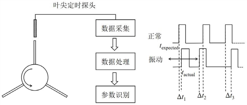
[0021] For the common blade tip timing system, when the blade sweeps the blade tip timing probe during the rotation process, the blade tip timing probe will receive a blade tip timing signal pulse. According to the blade tip timing signal pulse, each The time it takes for a blade to turn to the probe. And when the blade is in the vibrating state, the time t for the blade tip to pass the probe every time it rotates actual will be different, by analyzing the arrival time t of the received blade tip timing signal pulse actual and expected tip arrival time t expected The difference between Δt i The change of the blade can be monitored, such as figure 1 As shown, in this way, the real-time detection of the health status of the blade can be realized.

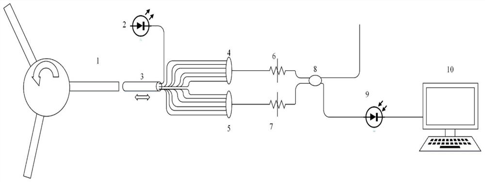
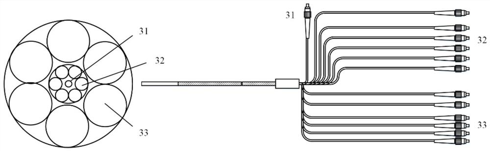
[0022] When the fiber optic bundle probe is used as the blade tip timing probe, the blade t...


PUM


Abstract

The invention discloses a tip timing measurement device and method based on an optical fiber bundle probe. The tip timing measurement device comprises a blade tip, a light source, the optical fiber bundle probe, a first optical fiber bundle combiner, a second optical fiber bundle combiner, a first optical fiber loss device, a second optical fiber loss device, an optical fiber coupler, a photoelectric detector and a display terminal; light emitted by the light source enters an emitting optical fiber of the optical fiber bundle probe; and when the blade tip sweeps over the optical fiber bundle probe, the light is reflected by the blade tip and then received by a first circle of receiving optical fiber and a second circle of receiving optical fiber, the received light is converged to corresponding optical fibers through the first optical fiber bundle combiner and the second optical fiber bundle combiner, the coupling ratio is adjusted through the first optical fiber loss device and the second optical fiber loss device, optical signals are coupled into the photoelectric detector through the optical fiber coupler, the optical signals are converted into electric signals, and tip timing signals are obtained. Compared with a traditional optical fiber bundle probe, the tip timing precision under the condition of tip gap fluctuation is improved.

Description

technical field [0001] The invention belongs to the field of blade tip timing of turbine blades, and relates to a blade tip timing measurement device and method, in particular to a blade tip timing measurement device and method based on an optical fiber bundle probe. Background technique [0002] As a key component of engines and steam turbines, the health of turbine blades seriously affects the operation of machines and the safety of operators. Due to factors such as exciting force and thermal expansion, the turbine blades will be damaged or even broken, which will endanger the operation safety of the turbine engine. Therefore, real-time health monitoring of turbine blades is required. Tip timing measurement is a commonly used real-time monitoring measurement method, including capacitive, microwave, magnetoresistive, and fiber optic bundle methods. Among them, the fiber optic bundle probe has great application advantages due to factors such as high precision, fast response...

Claims


Application Information

Patent Timeline
IPC IPC(8): G01H9/00G01M13/00
CPCG01H9/004G01M13/00Y02E10/72
Inventor 柴全陈余马占宇田野张建中
Owner HARBIN ENG UNIV
Why Eureka
Try Eureka