Yunbo torque sensor

A torque sensor, Yunbo's technology, applied in the field of sensors and modern sensors, can solve the problems of difficult to maintain the service life of the sensor, low power conversion efficiency, large magnetic resistance, etc., and achieve the effect of novel and unique design concept

Active Publication Date: 2020-12-25
陈会良
View PDF5 Cites 0 Cited by
  • Summary
  • Abstract
  • Description
  • Claims
  • Application Information

AI Technical Summary

Problems solved by technology

[0004] The existing phase-difference torque sensor has been gradually eliminated due to its bulky volume and poor torque measurement accuracy in low-speed and high-speed areas
[0005] Due to the dynamic friction of the conductive ring in the existing slip ring torque sensor, it is easy to cause heating and wear of the conductive ring assembly; especially when the domestic slip ring torque sensor rotates at a speed exceeding 3000 rpm, the use of the sensor The lifespan is difficult to maintain for about a year; but the small size is its biggest market advantage
[0006] The electromagnetic coil type torque sensor of the prior art uses an open-loop magnetic circuit structure instead of the conductive ring assembly, but the reluctance of the magnetic flux between the air-gap interface layers becomes larger, so that the electrical energy of the primary coil is coupled to the electrical energy of the secondary coil low conversion efficiency
In addition: the non-closed magnetic circuit is prone to electromagnetic radiation and electromagnetic interference from the outside world and other technical defects, and the reactance Z value of the electromagnetic wire coil is large, the frequency response speed is slow, and it is difficult to achieve real-time measurement of high-speed torque. The volume and shape of the sensor are several times larger than the slip ring torque sensor
[0007] Both the slip ring type torque sensor and the electromagnetic coil type torque sensor use the principle torque measurement technology that the strain gauge is pasted on the torque detection shaft: so the technical pain point of [static and dynamic electric energy coupling] cannot be avoided

Method used


Image

  • Yunbo torque sensor
  • Yunbo torque sensor
  • Yunbo torque sensor

Examples


Embodiment Construction

[0020] The present invention will be further elaborated below in conjunction with the embodiments shown in the accompanying drawings.

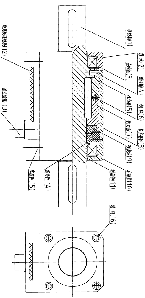
[0021] figure 1 A schematic diagram of the overall structure provided by this embodiment, the Yunbo torque sensor is composed of four parts: a sensor housing assembly, a torque shaft assembly, a deformable body force measuring assembly, and a base assembly;

[0022] in figure 1 The sensor housing assembly realizes the bearing of the torque rotating shaft and the base;

[0023] in figure 1 The torque shaft assembly realizes the transformation of the relationship between the axial displacement of the force transmission sleeve ΔL and the function of the torsion angle ψ;

[0024] in figure 1 A circuit processing module (12) is built in the base assembly to realize the logic processing of the power supply of the strain gauge bridge and the torque signal and output through the aviation socket (13) interface.

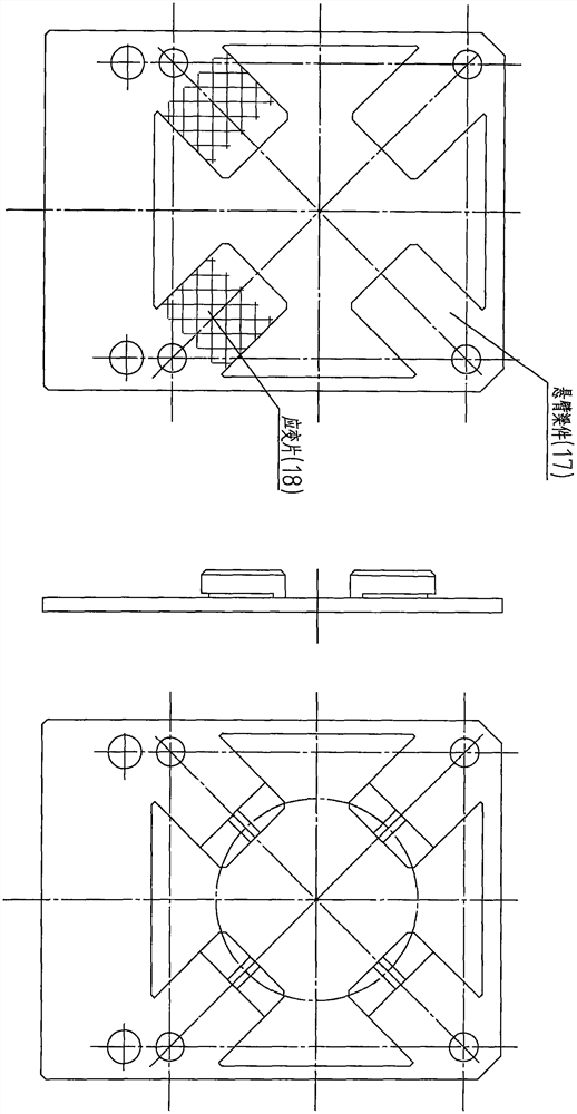
[0025] figure 2 It is a schemati...


PUM

PropertyMeasurementUnit
diameteraaaaaaaaaa

Abstract

The invention relates to a Yunbo torque sensor. The Yunbo torque sensor comprises a torque sensor shell assembly, a torque shaft body assembly, a cantilever beam group force measurement assembly and abase assembly; the torque shaft body assembly converts a torque angle psi into an axial displacement variable quantity delta L of a small part of a force transmission sleeve through a thrust sleeve fastened on a torque shaft (1) and the force transmission sleeve axially sliding and falling on the torque shaft (1), and the axial displacement variable quantity delta L of the force transmission sleeve further acts on a cantilever sheet beam of the cantilever beam group force measurement assembly to output torque in real time. According to the Yunbo torque sensor, based on a strain gauge torque measurement principle technology, the technical scheme of the new concept of 'the torque shaft not sticking to a strain gauge' is adopted, and the pain point demands for the small size, the high rotating speed and the long service life of the torque sensor are met.

Description

technical field [0001] The invention relates to a sensor; specifically, it is a Yunbo torque sensor with a brand-new technical solution; it belongs to the technical field of modern sensors. [0002] technical background [0003] The torque sensor products in the prior art usually fall into three categories: phase difference torque sensor, slip ring torque sensor and electromagnetic coil torque sensor. [0004] The phase-difference torque sensor in the prior art has been gradually eliminated due to its bulky size and poor torque measurement accuracy in low-speed and high-speed regions. [0005] Due to the dynamic friction of the conductive ring in the existing slip ring torque sensor, it is easy to cause heating and wear of the conductive ring assembly; especially when the domestic slip ring torque sensor rotates at a speed exceeding 3000 rpm, the use of the sensor It is difficult to maintain a lifespan of about one year; but its small size is its biggest market advantage. ...

Claims


Application Information

Patent Timeline
Patent Type & Authority Applications(China)
IPC IPC(8): G01L3/10
CPCG01L3/105
Inventor 陈会良邓莀苒陈恰
Owner 陈会良
Why Eureka
Try Eureka