Automatic assembling and welding device for heat pipe radiator machining

A heat pipe radiator and automatic assembly technology, which is applied in auxiliary devices, metal processing, welding equipment, etc., can solve problems such as time-consuming, laborious, troublesome, and affect welding work efficiency, and achieve the effect of improving welding efficiency

Inactive Publication Date: 2020-12-29
泉州市高谦机械产品有限公司
View PDF0 Cites 7 Cited by
  • Summary
  • Abstract
  • Description
  • Claims
  • Application Information

AI Technical Summary

Problems solved by technology

[0003] At present, during the production and processing of heat pipe radiators, a welding device is required to assemble and weld multiple heat pipes. In the existing welding device, the welding head and the welding base are fixed installations. However, when the heat pipes of the heat pipe radiator are assembled and welded , not in the same direction or angle, so when the heat pipe is welded, it is necessary to manually adjust the angle and position of the heat pipe back and forth, which is very troublesome and time-consuming, which greatly affects the efficiency of the welding work

Method used


Image

  • Automatic assembling and welding device for heat pipe radiator machining
  • Automatic assembling and welding device for heat pipe radiator machining
  • Automatic assembling and welding device for heat pipe radiator machining

Examples


Embodiment 1

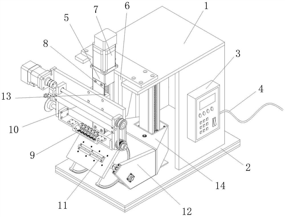
[0034] see figure 1 As shown, the present invention provides an automatic assembly and welding device for heat pipe radiator processing through improvement, including a cabinet 1, a support base 2, a control panel 3, a power cord 4, a frame 5, a fixed rear frame 6, a first Motor 7, screw mandrel 8, welding head 9, direction reversing device 10, welding base 11, angle adjustment mechanism 12, sliding block 13 and position adjustment mechanism 14, the supporting base 2 is installed on the bottom of cabinet 1, is used for supporting, and the right side The middle part is equipped with a control panel 3, which can be used to control the energized components of the device to work. The control panel 3 is connected with a power cord 4, which can be connected to an external power supply to provide power for the device. The rear side of the frame 5 is installed on the The front end of the chassis 1 and the top are equipped with a first motor 7, and a screw 8 is installed on the inside. T...

Embodiment 2

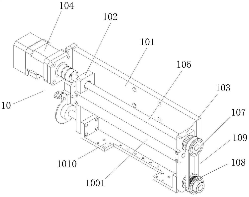
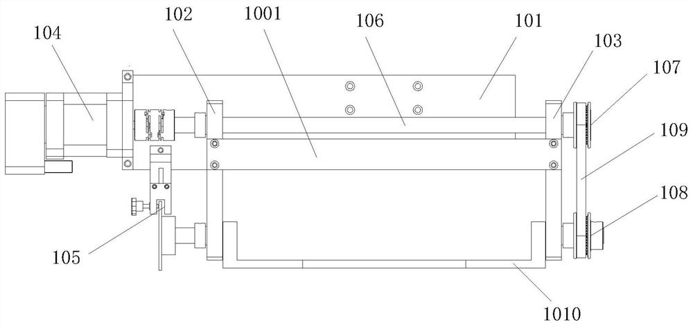
[0041] The present invention provides an automatic assembly and welding device for heat pipe radiator processing through improvement. The rear end of the stop mechanism 105 is fixed to the mounting plate 101, and the stop mechanism 105 can be fixed through the mounting plate 101 to ensure its stability. , the output shaft of the second motor 104 is connected to one end of the first rotating shaft 106 through a shaft coupling, so that after the second motor 104 works, the rotation of the output shaft can drive the first rotating shaft 106 to rotate through the transmission of the shaft coupling, The first runner 107 and the second runner 108 are arranged on the right side of the right vertical plate 103, which facilitates the transmission work of the first runner 107 and the second runner 108. The longitudinal bevel gear 148 and the transverse bevel gear 146 are perpendicular to each other. Mesh, make the 4th electric motor 143 work and drive the 2nd rotation shaft 145 to rotate...


PUM


Abstract

The invention discloses an automatic assembling and welding device for heat pipe radiator machining. The automatic assembling and welding device comprises a case, a support base, a control panel, a power cable, a rack, a fixed rear frame, a first motor, a lead screw, a welding head, a direction overturning device, a welding base, an angle adjusting mechanism, a sliding block and a position adjusting mechanism. Through arrangement of the direction overturning device, an overturning frame drives the welding head to conduct overturning adjustment in the direction; the angle adjusting mechanism isarranged, so that the angle of the welding base can be adjusted; meanwhile, the position adjusting mechanism is arranged, and can enable the position of the welding base to be adjusted up and down, so that the welding head and the welding base can conduct welding work in different directions, angles and positions, and the welding efficiency is improved.

Description

technical field [0001] The invention relates to the field related to the processing of heat pipe radiators, in particular to an automatic assembly and welding device for processing heat pipe radiators. Background technique [0002] Heat pipe radiator is a new product produced by using heat pipe technology to make significant improvements to many old radiators or heat exchange products and systems. The thermal resistance of the radiator is determined by the thermal conductivity of the material and the effective area within the volume. Under the condition of natural convection cooling, the performance of the heat pipe radiator can be improved by more than ten times than that of the solid radiator. Therefore, the heat pipe radiator can improve the safety and reliability of electrical equipment and has a wider application range. [0003] At present, during the production and processing of heat pipe radiators, a welding device is required to assemble and weld multiple heat pipes....

Claims


Application Information

Patent Timeline
Patent Type & Authority Applications(China)
IPC IPC(8): B23K37/00B23K37/02
CPCB23K37/00B23K37/02B23K37/0211B23K37/0252B23K2101/14
Inventor 钟兴炳
Owner 泉州市高谦机械产品有限公司
Why Eureka
Try Eureka