Overhead thermal control system of new energy passenger car

A thermal control system and new energy technology, applied in electric vehicles, vehicle energy storage, vehicle components, etc., can solve problems such as high cost, increased vehicle weight, energy waste, etc., and achieve easy maintenance, guaranteed reliability, and low price Effect

Pending Publication Date: 2020-12-29
SHANGHAI SUNLONG BUS
View PDF0 Cites 0 Cited by
  • Summary
  • Abstract
  • Description
  • Claims
  • Application Information

AI Technical Summary

Problems solved by technology

At present, the cooling and heating of new energy buses use a set of heat pump air conditioners, which leads to the fact that the air conditioners cannot achieve the highest energy efficiency when cooling or heating, especially the energy efficiency is lower when heating: because the hot air of the air conditioner is from the top of the vehicle When the air duct blows out, the hot air has a low density and converges toward the upper part of the compartment, which results in a lower temperature in the lower part of the compartment, which not only affects the comfort of passengers, but also increases the energy consumption of the air conditioner, which in turn affects the battery life of the vehicle
Therefore, the existing new energy buses have the following shortcomings in the compartment and battery thermal management technology: (1) The cost of independently setting up the battery thermal management unit is high, and additional installation space is required, which will increase the weight of the vehicle, which is not conducive to the development of new energy vehicles. Energy Saving and Consumption Reduction of Passenger Cars
(2) The heat pump electric air conditioner is used for the cooling and heating of the compartment. The air conditioner cannot achieve the highest energy efficiency due to the need to balance cooling and heating, and the hot air of the air conditioner is blown from the air duct on the roof, which is not conducive to vehicle energy saving and ride comfort.
(3) The thermal management of the vehicle compartment and the battery are separate independent devices, which does not realize the centralized thermal management of the vehicle, which is likely to cause energy waste

Method used


Image

  • Overhead thermal control system of new energy passenger car

Examples


Embodiment

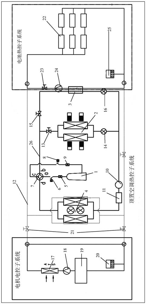
[0025] Such as figure 1 Shown is the overall system structure diagram of the present invention, the thermal control system includes overhead air conditioner thermal control subsystems connected to each other, the connecting pipes in the overhead air conditioner thermal control subsystem adopt refrigerant pipeline 26, battery thermal control subsystem and The motor electronic control subsystem and the thermal control subsystem of the overhead air conditioner include a compressor 1, an air conditioner evaporator 2, a plate heat exchanger 3 and an air conditioner condenser 4, and the compressor 1 passes through the pressure relief valve 5 and the high pressure switch 6 in sequence The port a of the one-way valve 7 is connected, the port c of the four-way valve 7 passes through the low-pressure switch 8 and the gas-liquid separator 9 in turn through another circuit and is connected to the compressor 1, and the port b of the four-way valve 7 passes through the air conditioner evapor...


PUM


Abstract

The invention relates to an overhead thermal control system of a new energy passenger car. The thermal control system comprises an overhead air conditioner thermal control sub system, a battery thermal control sub system and a motor electrical control sub system interconnected. The overhead air conditioner thermal control sub system comprises a compressor, an air conditioner evaporator, a plate type heat exchanger and an air conditioner condenser. The compressor is connected to a port a of a four-way valve through a pressure relief valve and a high pressure switch successively, a port c of thefour-way valve is connected to the compressor through a low voltage switch and a gas-liquid separator successively in another loop, a port b of the four-way valve is connected to level glass throughthe air conditioner evaporator and the plate type heat exchanger successively, the level glass is connected to a port d of the four-way valve through a drier and the air conditioner condenser successively, and the air conditioner condenser is further connected to the battery thermal control sub system and the motor electrical control sub system separately through a cooling rubber tube. Compared with the prior art, the system has the advantages of being free of occupied space, low in failure rate and the like.

Description

technical field [0001] The invention relates to the technical field of automobile thermal control, in particular to a roof-mounted thermal control system for a new energy passenger car. Background technique [0002] At present, the battery thermal management technology adopted by new energy buses mainly adopts the technical solution of independent air-conditioning units. This technical solution is equipped with a set of air-conditioning units for the battery of the new energy bus, which cools the battery in summer and heats the battery in winter, so as to ensure the stability of the battery temperature. However, this technical solution requires additional air-conditioning installation space reserved for the whole vehicle. Therefore, not only the occupied space increases, but also the weight of the whole vehicle increases, which is not conducive to the overall simplification of the design and energy saving of the new energy bus. [0003] Air conditioning is an important ener...

Claims


Application Information

Patent Timeline
Patent Type & Authority Applications(China)
IPC IPC(8): B60H1/00B60H1/32B60L58/24
CPCB60H1/00321B60H1/00392B60H1/00485B60H1/00642B60H1/3204B60L58/24Y02T10/70
Inventor 王靖张宇博云大笑
Owner SHANGHAI SUNLONG BUS
Why Eureka
Try Eureka