Tenon type insertion novel fabricated steel-concrete composite joint

A combined node and prefabricated technology, applied in building types, truss structures, protective buildings/shelters, etc., can solve the problem that the post-cast concrete cannot be vibrated and compacted, the construction period and labor cost increase, and the sleeve grouting process Cumbersome and other problems, to achieve the effect of strong concrete holding shear resistance, good overall connectivity, and promoting sustainable development

Active Publication Date: 2020-12-29
QINGDAO TECHNOLOGICAL UNIVERSITY
View PDF5 Cites 7 Cited by
  • Summary
  • Abstract
  • Description
  • Claims
  • Application Information

AI Technical Summary

Problems solved by technology

But at the same time, there are also the following problems: (1) During the installation of prefabricated columns, in order to smoothly insert the longitudinal steel bars into the grouting sleeve, the hoisting accuracy is high; (2) The core area of ​​the node is densely packed with steel bars, which makes binding difficult. The construction period and labor cost increase; (3) the post-cast concrete in the core area of ​​the node cannot be vibrated and compacted, and the construction quality is difficult to guarantee; (4) the subsequent sleeve grouting process is cumbersome, the grouting quality is difficult to guarantee and the labor cost is increased

Method used


Image

  • Tenon type insertion novel fabricated steel-concrete composite joint
  • Tenon type insertion novel fabricated steel-concrete composite joint
  • Tenon type insertion novel fabricated steel-concrete composite joint

Examples


Embodiment 1

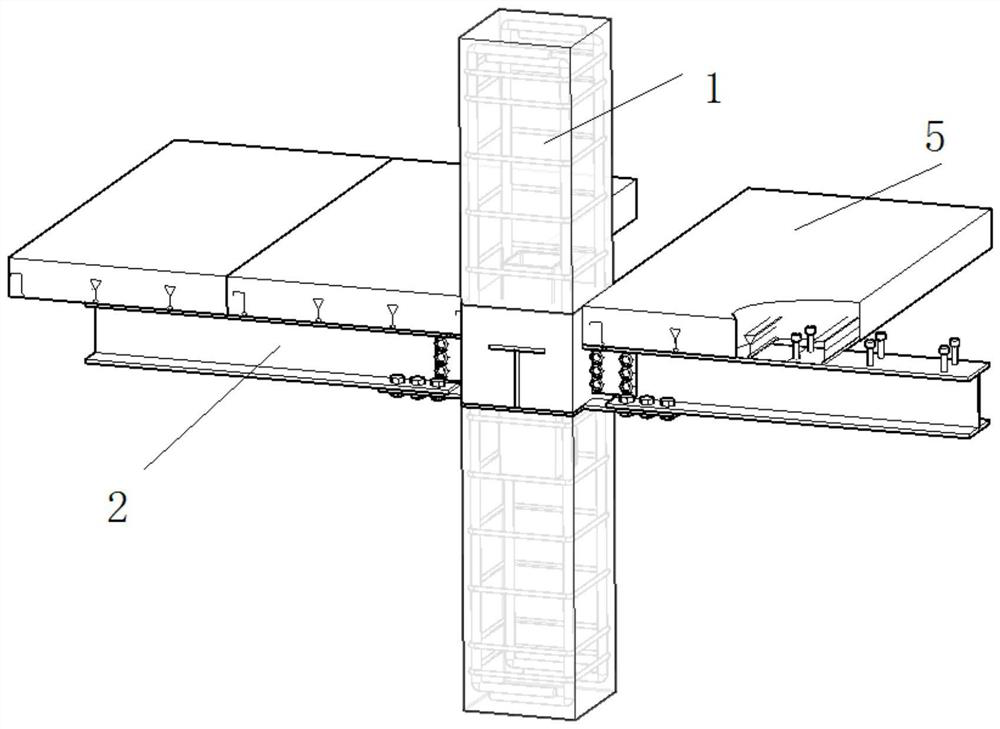
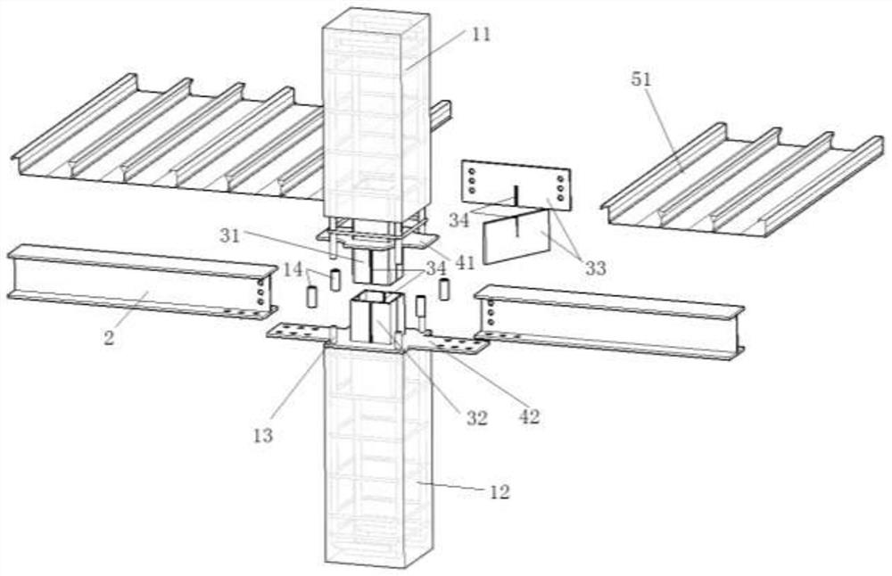
[0047] Such as Figure 1-2 As shown, the new prefabricated steel-concrete composite node with tenon-type insertion according to the present invention includes reinforced concrete column 1, H-shaped steel beam 2, tenon-type insertion assembly 3, circumferential connecting plate 4 and composite floor slab 5.

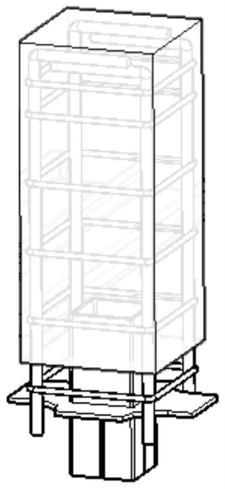
[0048] Among them, the reinforced concrete column includes an upper reinforced concrete column 11 and a lower reinforced concrete column 12, wherein the reinforcement cage includes stirrups and longitudinally stressed steel bars 13, and the upper reinforced concrete column 11 and the lower reinforced concrete column 12 pass through the tenon-type plug-in assembly 3 Connection, the upper reinforced concrete column 11 and the lower reinforced concrete column are connected with the H-shaped steel beam 2 through the tenon-type plug-in assembly 3 and the ring connection plate.

[0049] The tenon joint assembly 3 includes the tenon joint inner sleeve 31 , the tenon joint outer s...

Embodiment 2

[0066] The difference between this embodiment and Embodiment 1 is that the cross-sections of the tenon-type insertion inner sleeve and the tenon-type insertion outer sleeve are both circular, and the others are the same as Embodiment 1. Such as Figure 10 shown.


PUM


Abstract

The invention relates to the field of building structures, and discloses a tenon type insertion novel fabricated steel-concrete composite joint. The tenon type insertion novel fabricated steel-concrete composite joint comprises a reinforced concrete column, an H-shaped steel beam, a tenon type insertion assembly, an annular connecting plate and a composite floor slab, the tenon type insertion assembly comprises a tenon type insertion inner sleeve, a tenon type insertion outer sleeve and a cross plate, the annular connecting plate comprises an upper flange annular connecting plate and a lower flange annular connecting plate, an upper reinforced concrete column body and a lower reinforced concrete column body are connected through the tenon type insertion assembly, the reinforced concrete column and the steel beam are connected through the tenon type insertion assembly and the annular connecting plate, and the composite floor slab is fixedly connected with the H-shaped steel beam. According to the tenon type insertion novel fabricated steel-concrete composite joint, steel beams in different directions can be flexibly connected through the tenon type insertion assembly and the annularconnecting plate in the core area, the bearing capacity and shear resistance of the joint core area can be remarkably improved, machining and prefabrication are easy and convenient, and good overallconnectivity, bearing capacity and anti-seismic property are achieved.

Description

technical field [0001] The invention relates to the field of building structures, in particular to a new assembled steel-concrete composite joint with mortise and tenon joints. Background technique [0002] Compared with traditional construction methods, prefabricated buildings have the advantages of high degree of industrialization, labor saving, energy saving and environmental protection, and have become an important direction for realizing green buildings and industrialization. [0003] In the prefabricated concrete frame structure, the complexity and reliability of the beam-column connection structure has become an important factor restricting the comprehensive promotion and application of the prefabricated concrete frame structure. [0004] During on-site assembly and construction, grouting sleeves are often used to connect beams and columns. This method has been widely used, and the connection quality is guaranteed to a certain extent. But at the same time, there are ...

Claims


Application Information

Patent Timeline
Patent Type & Authority Applications(China)
IPC IPC(8): E04B1/38E04B1/58E04C3/34E04C3/04E04B5/00E04B1/94E04B1/98E04H9/02
CPCE04B1/38E04B1/58E04B1/94E04B1/98E04B5/00E04C3/04E04C3/34E04H9/021E04H9/025
Inventor 吴成龙刘继明牟犇于素健
Owner QINGDAO TECHNOLOGICAL UNIVERSITY
Why Eureka
Try Eureka