
A titanium alloy exhaust tongue valve

A titanium alloy and flap valve technology, which is applied to exhaust devices, lift valves, valve devices, etc., can solve the problems of valve cooling water jacket corrosion, corrosion leakage, valve disc position compensation failure, etc., to facilitate maintenance and replacement, improve Corrosion resistance, impact reduction effect

Active Publication Date: 2022-04-08
CHINA SHIP DEV & DESIGN CENT
View PDF13 Cites 0 Cited by
  • Summary
  • Abstract
  • Description
  • Claims
  • Application Information

AI Technical Summary

Problems solved by technology

High-temperature flue gas leads to serious carbon deposits inside the exhaust inner tongue valve. The exhaust inner tongue valve used in active boats is mainly made of steel materials. Users have repeatedly reported that the cooling water jacket of the valve is seriously corroded, the sealing effect of the valve disc is poor, and the operating torque is large. , easy stuck, difficult maintenance and other problems
After analysis and research, it is believed that the cause of the problem is that the valve disc and components of the tongue valve are made of carbon steel, and there is serious corrosion. The valve disc fastener and ball head structure are rusted, which leads to the failure of the position compensation of the valve disc, and the sealing is not good. Strict; the exhaust inner tongue valve of active boats is driven by a hydraulic motor worm gear mechanism, which cannot provide the pre-tightening force when the valve disc is closed, and will also lead to poor sealing; the cooling water jacket of the tongue valve shell is made of steel material, which is cooled by seawater Corrosion causes water leakage; the worm wheel and worm parts used for grinding are all steel materials, the material matching is not good, and the metal properties are very similar, which leads to serious adhesive wear when forming friction pairs, and occlusion occurs after a long period of use , causing the moving parts to jam

Method used


Image

  • A titanium alloy exhaust tongue valve
  • A titanium alloy exhaust tongue valve
  • A titanium alloy exhaust tongue valve

Examples


Embodiment Construction

[0026] The present invention will be further described below in conjunction with accompanying drawing.

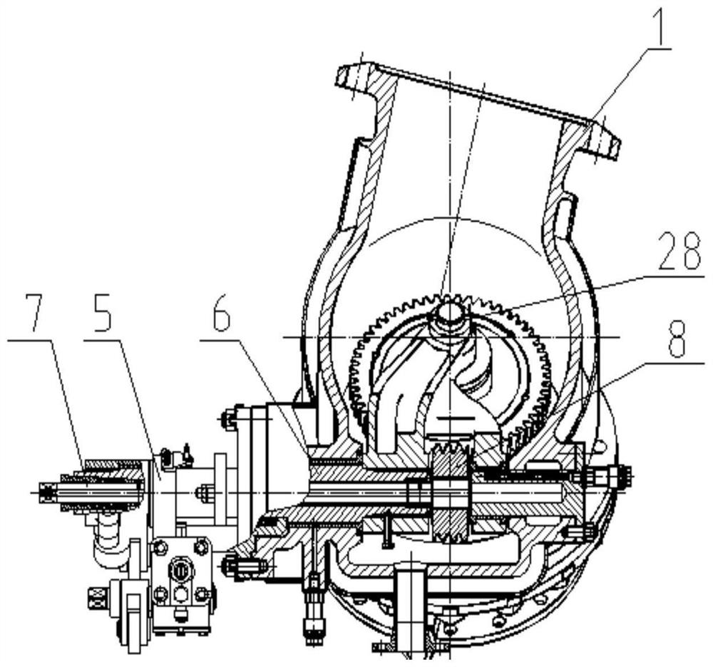
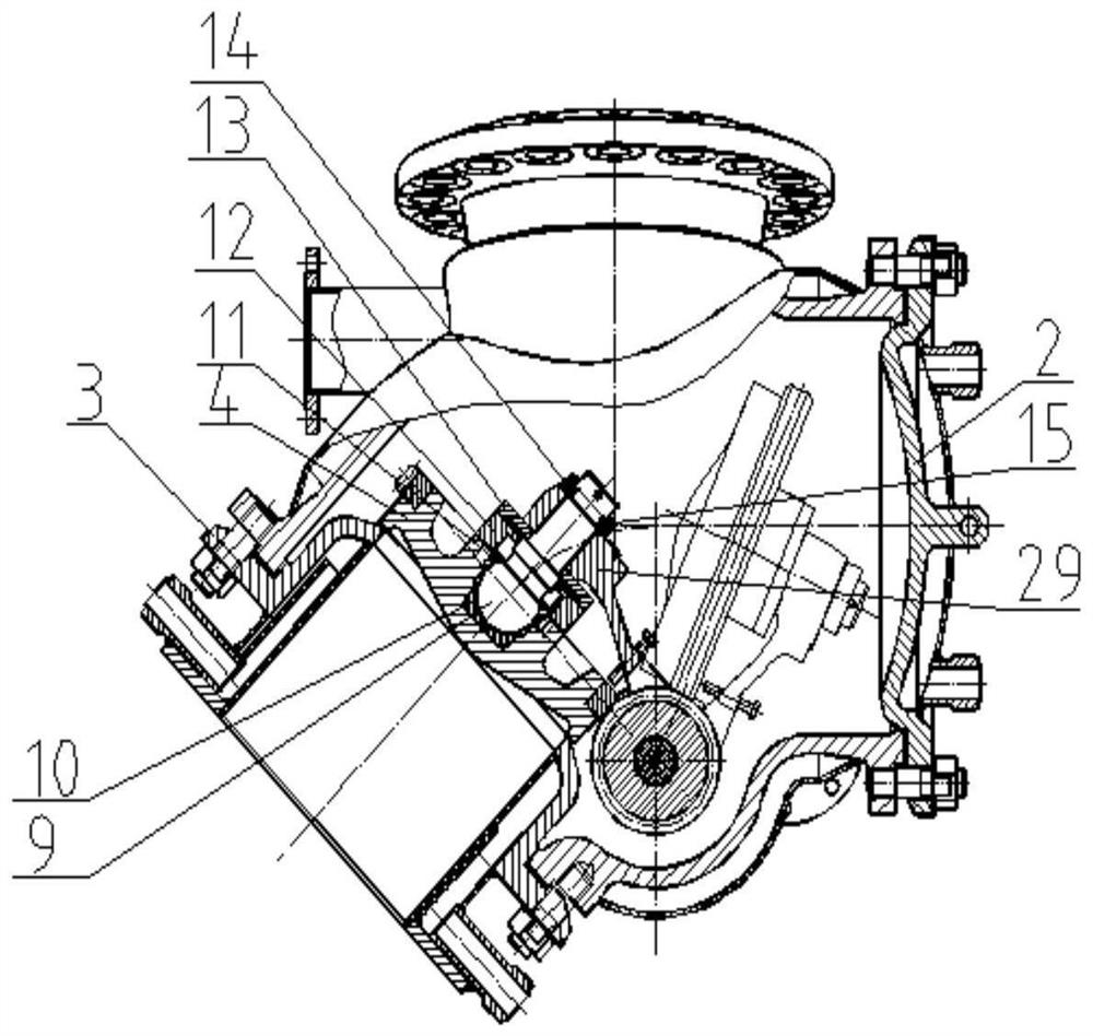
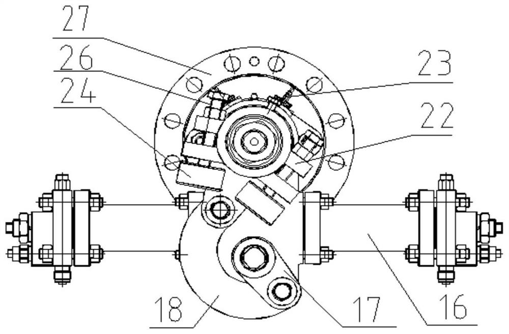
[0027] like figure 1 , 2 As shown, this embodiment provides a titanium alloy exhaust tongue valve, which includes a housing 1, a valve cover 2, a valve seat 3 and a valve disc 4, and also includes a hollow shaft 6, a long shaft 7, a hydraulic actuator 5, and a lever 29. The hollow shaft 6 is set on the long shaft 7, and the two move independently. One end of the hollow shaft 6 is connected with the lever 29, and the other end of the lever 29 is connected with the valve disc 4. The hollow shaft 6 passes through The hydraulic actuator 5 is driven to realize the opening or closing of the valve disc relative to the valve seat 3, and the tail end of the long axis 7 is connected with the valve disc 4 through a worm gear mechanism to realize the sealing connection between the valve disc and the valve seat.

[0028] like image 3 , 4 As shown, the hydraulic actuator 5 includes ...


PUM


Abstract

The invention discloses a titanium alloy exhaust tongue valve, which includes a shell, a valve cover, a valve seat and a valve disc, and is characterized in that it also includes a hollow shaft, a long shaft, an actuator, and a lever, and the hollow shaft is sleeved on the long On the shaft, the two move independently. One end of the hollow shaft is connected to the lever, and the other end of the lever is connected to the valve disc. The hollow shaft is driven by the actuator to realize the opening or closing of the valve disc relative to the valve seat. , the tail end of the long axis is connected with the valve disc through a worm gear mechanism, so as to realize the sealing connection between the valve disc and the valve seat. The titanium alloy exhaust tongue valve of the present invention can realize the self-locking of the valve position when the valve disc is opened and closed, has the effect of "increasing force and decelerating", realizes the stable opening and closing of the valve disc, and reduces the impact of collision.

Description

technical field [0001] The invention belongs to the exhaust tongue valve technology of the intake and exhaust system of the marine diesel engine, and in particular relates to a titanium alloy exhaust inner tongue valve used for the intake and exhaust system of the marine diesel engine. Background technique [0002] The exhaust tongue valve is a locking device used in the exhaust system of marine diesel engines. At present, the common configuration mode at home and abroad is to set up two tongue valves, which are the exhaust outer tongue valve and the exhaust inner tongue valve. The exhaust external tongue valve is arranged on the exhaust pipe of the superstructure of the ship. Due to the distance from the exhaust port of the diesel engine and the cooling of the seawater outside the ship, the temperature of the internal flue gas drops rapidly. [0003] The exhaust internal tongue valve is a locking device located on the pressure-resistant body, which is used to prevent seawat...

Claims


Application Information

Patent Timeline
Patent Type & Authority Patents(China)
IPC IPC(8): F16K1/20F16K1/32F16K1/36F16K27/02F16K27/08F16K31/163F16K31/52F16K31/54F01N13/00
CPCF16K1/2007F16K1/36F16K1/32F16K27/0227F16K27/08F16K31/1635F16K31/521F16K31/54F01N13/00
Inventor 孙瑞康周睿白宗良刘伟李建
Owner CHINA SHIP DEV & DESIGN CENT
Learn More