
Channel silt and flow measuring system

A channel and flow measurement technology, applied in the field of measurement systems, can solve problems such as affecting the quality and efficiency of hydrological testing, limited ability to measure the environment, and affecting measurement accuracy, so as to reduce the probability of exposure to sunlight and rain, maintain stable measurement accuracy, The effect of high measurement accuracy

Pending Publication Date: 2020-12-29
唐山海森电子股份有限公司
View PDF9 Cites 0 Cited by
  • Summary
  • Abstract
  • Description
  • Claims
  • Application Information

AI Technical Summary

Problems solved by technology

[0003] The commonly used measuring mechanism is that the measuring instrument is set on the traction cable and moves horizontally on the cable. Various sensors are installed in the measuring instrument, including liquid level sensor, flow rate sensor, etc. Since the water in the channel is flowing, the sensor During the measurement process, it is easy to be affected by the water flow, which will affect the measurement accuracy.
[0004] In addition, the vertical automatic measurement system is gradually emerging, and the degree of water conservancy information is also improving, but the ability to deal with complex measurement environments is still limited. Some measuring instruments are exposed to open environments for a long time, which may easily cause damage to their internal components. This has affected the quality and efficiency of hydrological survey work to a certain extent

Method used


Image

  • Channel silt and flow measuring system
  • Channel silt and flow measuring system
  • Channel silt and flow measuring system

Examples


Embodiment 1

[0040] Embodiment 1: The ultrasonic transducer 13 is installed on the lower surface of the liquid level gauge, and two trigger ports are arranged along the axial direction of the liquid level gauge.

Embodiment 2

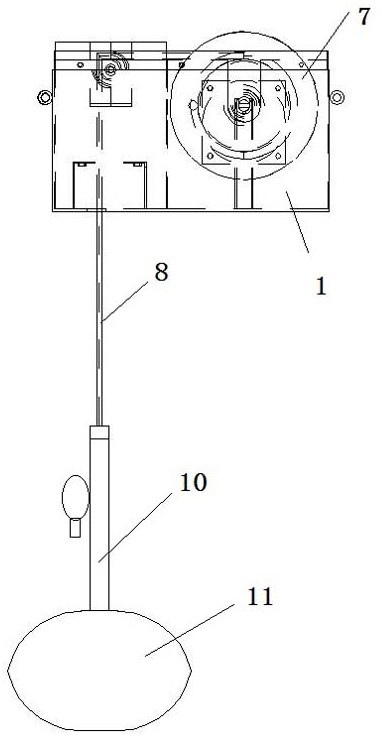
[0041] Embodiment 2: The ultrasonic transducer 13 is installed on the lower surface of the lead fish body, and two trigger ports are arranged along the axial direction of the lead fish body.

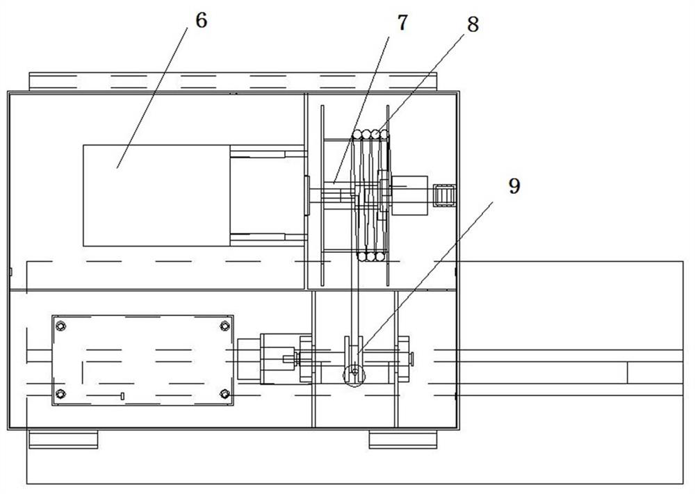
[0042]During use, the system disclosed by the present invention is used for real-time multi-point automatic measurement and early warning of channel section flow velocity, water level and silting conditions. When in use, it can realize vertical multi-point measurement, connect with the cloud through the communication structure, control the main body and the cloud computing center to realize the precise calculation of edge and cloud integration. When idle, the measuring device can be moved to the hidden box in time for hidden protection, reducing its long-term exposure in the field environment, prolonging its service life and reducing the difficulty of maintenance.


PUM


Abstract

The invention discloses a channel silt and flow measuring system. The channel silt and flow measuring system comprises a moving mechanism, a lifting mechanism and a sensor set; a fixing sleeve and a sliding sleeve are arranged on the two sides outside a shell in the moving mechanism, the fixing sleeve is fixedly connected with a steel cable, and the sliding sleeve is in sliding fit with the steelcable; a driving motor and a roller set in the lifting mechanism are arranged in the shell and are in connection transmission, one end of a lifting rope is wound on the roller set, and the other end of the lifting rope is connected with the sensor set; and a liquid level meter and an ultrasonic transducer in the sensor set are correspondingly arranged on a fish lead assembly, and the fish lead assembly is connected with the lifting rope. A measuring device is driven by the measuring device to perform transverse fixed-point displacement and transverse multi-point measurement without blockage; each sensor is always kept vertical to the water flow cross section under the action of lead fish and gravity, so that the sensors cannot deflect or be cheap due to the impact of water flow caused by inclination of a measuring machine, and the measuring precision is high and stable; and transparent ultrasonic waves are adopted as a flow velocity measurement mode, the precision is high, and the working efficiency is high.

Description

technical field [0001] The invention relates to a measurement system, in particular to a split channel silt and flow measurement system with a hidden protective structure. Background technique [0002] During the use of open channels, sedimentation causes dynamic changes in the cross-section, which directly restricts the accuracy and form of flow measurement. The most common measurement method is the vertical flow measurement method, that is, a steel cable is erected on both sides of the channel measurement section, the measuring instrument moves on the cable, and the vertical line measurement and control points are evenly arranged on the cable track, and the sag measurement device is dropped after reaching the measurement and control point. , measure the water level after touching the bottom, and when it rises to different liquid levels on the vertical line, it can stably measure and record the flow velocity and water level at the position, forming multiple measurement unit...

Claims


Application Information

Patent Timeline
IPC IPC(8): G01F1/66G01F23/296G01V1/00
CPCG01F1/66G01F23/296G01V1/00
Inventor 李宝来郭勇崔利刚幺小亮黄蕊马丽丽王明豪孙雪峰刘东英鲍聪
Owner 唐山海森电子股份有限公司
Learn More