

Large-scale structure hydrodynamic coefficient measuring device and method
A technology of hydrodynamic coefficient and large-scale structure, applied in the field of offshore oil machinery, can solve the problems such as the difficulty of combining the economy and accuracy of hydrodynamic coefficient well, the accuracy of hydrodynamic coefficient is not high, and the upflow area cannot be maintained, etc. Achieve the effect of reducing operating costs and risks, improving operating efficiency and safety factor, and reducing experimental costs
- Summary
- Abstract
- Description
- Claims
- Application Information
AI Technical Summary
Problems solved by technology
Method used
Image

Examples
Embodiment Construction
[0044] In order to make the technical solutions and advantages of the present invention clearer, the exemplary embodiments of the present invention will be further described in detail below in conjunction with the accompanying drawings. Apparently, the described embodiments are only a part of the embodiments of the present invention, and are not exhaustive of all the embodiments. And in the case of no conflict, the embodiments and the features in the embodiments of the present invention can be combined with each other.
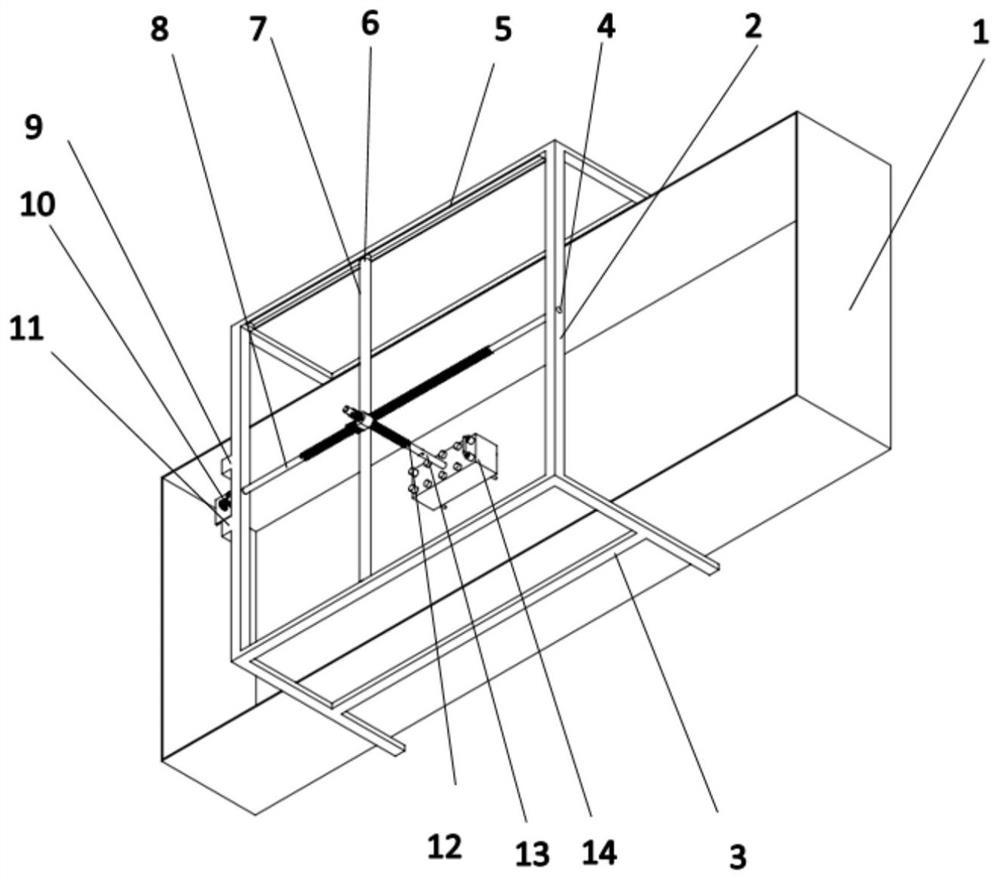
[0045] The inventor noticed in the course of the invention that when a small boat is used to drag the model at a fixed speed to measure the hydrodynamic coefficient, the frontal area in the water cannot be maintained, resulting in low accuracy of the measured hydrodynamic coefficient, thus affecting the actual Engineering is misleading. At present, the method of measuring the additional mass coefficient is mainly used to connect the four corners of the manifo...
PUM
 Abstract
Description
Claims
Application Information