Automatic thermoplastic packaging device for lithium battery
A lithium battery, automatic technology, applied in packaging, wrapping paper, shrinkage of wrapping paper, etc., can solve problems affecting efficiency, heavy workload, high safety hazards, etc., and achieve the effect of improving packaging quality
- Summary
- Abstract
- Description
- Claims
- Application Information
AI Technical Summary
Problems solved by technology
Method used
Image
Examples
Embodiment 1
[0064] An automatic thermoplastic packaging device for lithium batteries, such as figure 1 As shown, it includes a bottom plate 1, a workbench 2, a motor 3, a transmission mechanism 4 and a thermoplastic mechanism 5, the top of the bottom plate 1 is connected with a workbench 2, the workbench 2 is connected with a transmission mechanism 4, and the top right side of the bottom plate 1 is connected with a The motor 3 and the transmission mechanism 4 cooperate with the motor 3 in transmission, and the eccentric position on the top front side of the bottom plate 1 is slidably connected with a thermoplastic mechanism 5 .
[0065]When the staff needs to pack the lithium battery, the lithium battery with the packaging bag can be placed on the transmission mechanism 4, and then the motor 3 is started to rotate to drive the transmission mechanism 4 to rotate and transmit the lithium battery, and the transmission mechanism 4 works to drive the lithium battery. The thermoplastic mechanis...
Embodiment 2
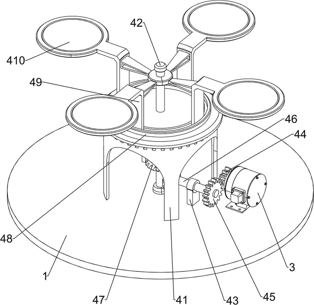
[0067] On the basis of Example 1, such as figure 2 and image 3 As shown, the transmission mechanism 4 includes a fixed bracket 41, a first rotating shaft 42, a first bearing column 43, a missing gear 44, a first spur gear 45, a second rotating shaft 46, a bevel gear assembly 47, a slide rail 48, and a supporting plate 49 and the placement tray 410, the top of the bottom plate 1 is connected with a fixed bracket 41, the top of the bottom plate 1 is rotatably connected with a first rotating shaft 42, the first rotating shaft 42 passes through the top of the fixed bracket 41 and is connected with it in a rotational manner, the right side of the bottom plate 1 top is provided with The first bearing column 43, the second rotating shaft 46 is connected on the first bearing column 43, the first spur gear 45 is connected on the right side of the second rotating shaft 46, the output shaft of the motor 3 is connected with a missing gear 44, and the missing gear 44 is connected with th...
Embodiment 3
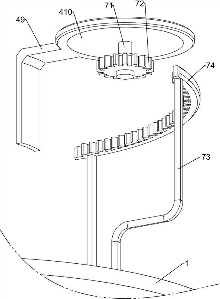
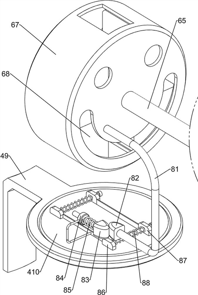
[0071] Such as Figure 4 to Figure 7 As shown, it also includes a blanking mechanism 6, and the blanking mechanism 6 includes a second bearing column 61, a third rotating shaft 62, a second spur gear 63, a second fixed column 64, a fourth rotating shaft 65, a transmission assembly 66, a fixed The frame 67 and the blanking plate 68, the left side of the top of the bottom plate 1 are symmetrically provided with a second bearing column 61, a third rotating shaft 62 is connected between the second bearing columns 61, and a second spur gear 63 is connected to the right side of the third rotating shaft 62, The second spur gear 63 meshes with the first spur gear 45. The left side of the top of the bottom plate 1 is connected with a second fixed column 64. The top of the second fixed column 64 is rotatably connected with a fourth rotating shaft 65. The left side of the fourth rotating shaft 65 is connected to the third rotating shaft. The transmission assembly 66 is connected between ...
PUM
 Abstract
Description
Claims
Application Information
 - R&D
- Intellectual Property
- Life Sciences
- Materials
- Tech Scout
- Unparalleled Data Quality
- Higher Quality Content
- 60% Fewer Hallucinations
Browse by: Latest US Patents, China's latest patents, Technical Efficacy Thesaurus, Application Domain, Technology Topic, Popular Technical Reports.
© 2025 PatSnap. All rights reserved.Legal|Privacy policy|Modern Slavery Act Transparency Statement|Sitemap|About US| Contact US: help@patsnap.com


