FRP balcony thermal bridge cutoff structure and method

A technology for thermally broken bridges and balconies, which is applied to balconies, building components, building structures, etc., can solve problems such as unfavorable control of structural bearing capacity and deflection, high research and development costs and cost of thermally broken bridges, and small internal force arms. Achieve the effect of convenient transportation and installation, controllable cost and reliable force

Inactive Publication Date: 2021-01-01
SOUTHEAST UNIV
View PDF6 Cites 1 Cited by
  • Summary
  • Abstract
  • Description
  • Claims
  • Application Information

AI Technical Summary

Problems solved by technology

[0006] Scholars previously conducted research on thermal break bridges for balconies, and achieved certain technical achievements and applications, but they mostly focused on balcony slabs with a thickness of 200-350 mm. At this stage, the thickness of concrete floor slabs in my country generally ranges from 100 to 350 mm. 140mm, the slab thickness is thinner, and in the case of thinner slab thickness, the internal moment arm between the tension member and the compression member is smaller, which is more unfavorable for the control of the structural bearing capacity and deflection. The balcony thermal break bridge configuration cannot be directly applied to our country
Moreover, most of the current research on thermal breakable bridges for balconies is produced in Europe, and there is a lack of research in related fields in China. The research and development costs and cost of thermal breakable bridges are relatively high, and the quotations of existing products are also relatively high.

Method used


Image

  • FRP balcony thermal bridge cutoff structure and method
  • FRP balcony thermal bridge cutoff structure and method
  • FRP balcony thermal bridge cutoff structure and method

Examples


Embodiment 1

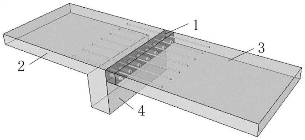
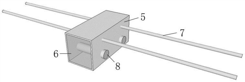
[0043] figure 2 It is a schematic diagram of the basic structure of a FRP balcony thermally broken bridge. In the embodiment, BFRP is selected as the main structural material. The thickness of the balcony plate is 130mm, and the span of the thermally broken bridge is 80mm. The diameter of the upper BFRP tension bar 7 is selected to be 20mm. The anchorage length is selected to be 500mm, the diameter of the lower large-diameter BFRP compressive reinforcement 8 is selected to be 40mm, and the length of insertion into the concrete is selected to be 20mm. In the example, XPS is selected as the thermal insulation filling material 6, which has low thermal conductivity and light weight, which can facilitate the transportation and construction of the thermal break bridge structure while ensuring the overall heat insulation capacity of the balcony thermal break bridge. The packaging part 5 is made of PVC, which wraps the periphery of the thermally broken bridge structure to reduce the ...

Embodiment 2

[0046] Figure 4 It is a schematic diagram of a reinforced structure of an FRP balcony thermally broken bridge containing shear plates. In the embodiment, BFRP is selected as the main structural material, and the cross-sectional dimensions and The length of the extension into the concrete is selected with figure 2 The basic structure of the FRP balcony thermal break bridge is the same. A shear plate 9 with a cross-section size of 50×5mm is added in the middle of the section of the thermally broken bridge. force.

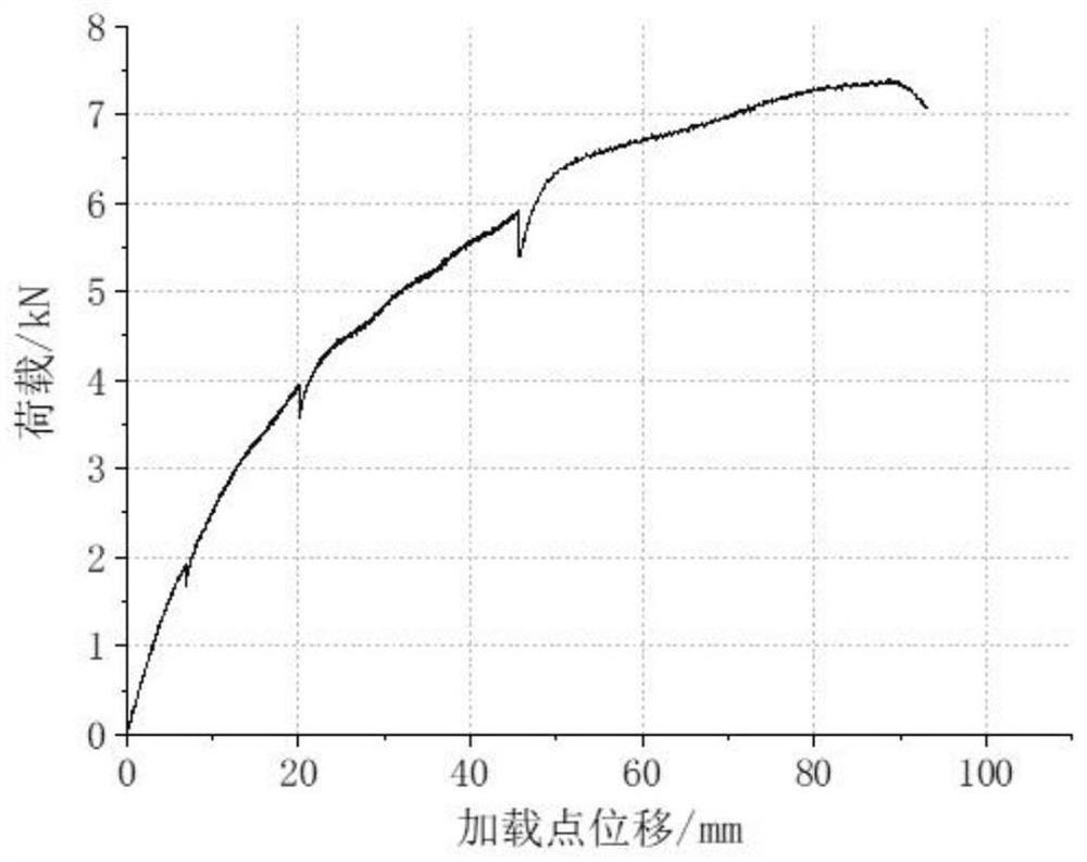
[0047] Figure 5 for Figure 4 The load-displacement curve of the segmental load-displacement curve of the reinforced structure of the FRP balcony thermally broken bridge with shear plates is shown. Here, a 300mm segment is selected for analysis. The segment contains two 20mm BFRP tension bars and two 40mm BFRP compression shear reinforcement, and a shear plate with a cross-sectional size of 50×5mm, the loading point is still selected to be 750mm away from the ...

Embodiment 3

[0049] Figure 6 It is a schematic diagram of an FRP balcony thermally broken bridge reinforcement structure with oblique connectors, and BFRP is selected as the main structural material in the embodiment. The cross-sectional size of the upper BFRP tension bar 7 and the lower large-diameter BFRP compression bar 8 and the length of the extension into the concrete are selected in accordance with the figure 2 The basic structure of the FRP balcony thermal break bridge is the same, and an additional BFRP oblique connector 10 with a diameter of 10mm is added, and the horizontal distance between its end and the edge of the concrete is 50mm.

[0050] Figure 7 for Figure 6 The load-displacement curve of the segmental load-displacement curve of the FRP balcony thermally broken bridge reinforced structure with oblique connectors is shown. Here, a 300mm segment is selected for analysis. The segment contains two 20mm BFRP tension bars and two 40mm BFRP compression reinforcement, and...


PUM

PropertyMeasurementUnit
thicknessaaaaaaaaaa
thicknessaaaaaaaaaa

Abstract

The invention discloses an FRP balcony thermal bridge cutoff structure and method. The FRP balcony thermal bridge cutoff structure comprises a tension piece, a compression piece, a heat preservation material and a packaging piece and further comprises a shear-resistant piece, wherein the packaging piece is filled with the heat preservation material; the tension piece is made of FRP rib materials and located on the upper portion of the packaging piece, the two ends of the tension piece stretch out of the packaging piece, the end stretching out of the packaging piece is used for stretching intoa main floor slab, and the other end stretching out of the packaging piece is used for stretching into a balcony slab; and the compression piece is made of FRP rib materials and located on the lower portion of the packaging piece, one end of the compression piece stretches out of the packaging piece, and the end stretching out of the packaging piece is used for stretching into the balcony slab. According to the FRP balcony thermal bridge cutoff structure, the excellent mechanical property and thermal property of FRP are fully utilized, and the completeness of a load force transmission path isguaranteed while building thermal bridges are reduced. Manufacturing is easy and convenient, the stress property is good, the heat insulation property is excellent, the local heat transfer amount of the thermal bridges can be effectively reduced, the risk of structural moisture condensation and mildewing is reduced, and the living comfort of a house is improved.

Description

technical field [0001] The invention relates to the technical field of civil engineering, in particular to a novel FRP balcony thermal break bridge structure. Background technique [0002] With the prominence of global energy and ecological environment issues, people are paying more and more attention to the issue of building energy consumption. In response to this, some developed countries such as Europe and the United States first proposed the concept of "passive building" and put forward specific requirements for building energy conservation. Among them, reducing building thermal bridges is a key point in passive building design. Thermal bridge refers to the part where the heat flow is relatively dense when the building exchanges heat with the outside world. Since the heat transfer coefficient of some parts is significantly greater than that of other parts, the heat is transferred from these parts concentratedly, and finally the heat flow in these parts is relatively dens...

Claims


Application Information

Patent Timeline
Patent Type & Authority Applications(China)
IPC IPC(8): E04B1/76E04B1/92E04B1/00E04B1/38
CPCE04B1/00E04B1/003E04B1/38E04B1/76E04B1/92
Inventor 汪昕吴智深王旭彤刘霞
Owner SOUTHEAST UNIV
Why Eureka
Try Eureka