
Detachable blade tip sealing ring of axial flow compressor and installation method

A technology for axial flow compressors and sealing rings, which is applied to the components of pumping devices for elastic fluids, mechanical equipment, non-variable pumps, etc., and can solve the problem of increasing the difficulty of cylinder processing, the difficulty, and the manufacturing and processing period Long and other problems, to achieve the effect of improving anti-stripping performance, reducing spraying difficulty, and shortening repair time

Active Publication Date: 2021-01-01
HANGZHOU TURBINE POWER GRP
View PDF4 Cites 0 Cited by
  • Summary
  • Abstract
  • Description
  • Claims
  • Application Information

AI Technical Summary

Problems solved by technology

Axial flow compressors have many stages, and the axial span of the compressor cylinder is usually large. The spraying process on the inner wall of the large cylinder is complicated and difficult, and the manufacturing and processing period is long. When the abradable coating loss is large, it needs When replacing, the entire cylinder needs to be processed, which is extremely inconvenient for later maintenance
If the tip sealing ring is simply installed in the same way as the stationary vane ring, that is, it is circumferentially drawn into the cylinder, due to the large number of stages of the axial flow compressor, the distance between the moving vane and the stationary vane is small, which will cause the cylinder The number of slots on the inner wall surface of the cylinder is large and the wall thickness between the slots is very small, which not only increases the difficulty of cylinder processing but also leads to low strength, which cannot be applied to actual product design

Method used


Image

  • Detachable blade tip sealing ring of axial flow compressor and installation method
  • Detachable blade tip sealing ring of axial flow compressor and installation method
  • Detachable blade tip sealing ring of axial flow compressor and installation method

Examples


Embodiment Construction

[0036] In the description of the present invention, it should be noted that the orientation or positional relationship indicated by the terms "upper", "inner", "outer", etc. is based on the orientation or positional relationship shown in the drawings. Such terms are only for the convenience of describing the present invention and simplifying the description, rather than indicating or implying that the referred device or element must have a specific orientation, be constructed and operated in a specific orientation, and thus should not be construed as limiting the present invention.

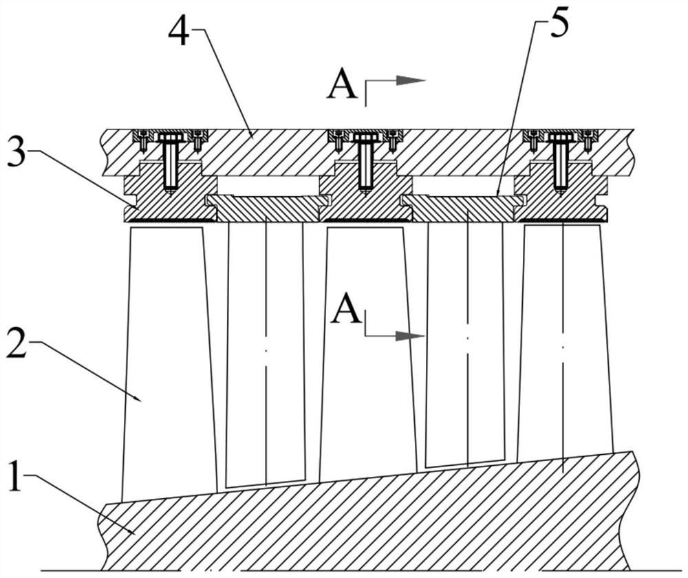
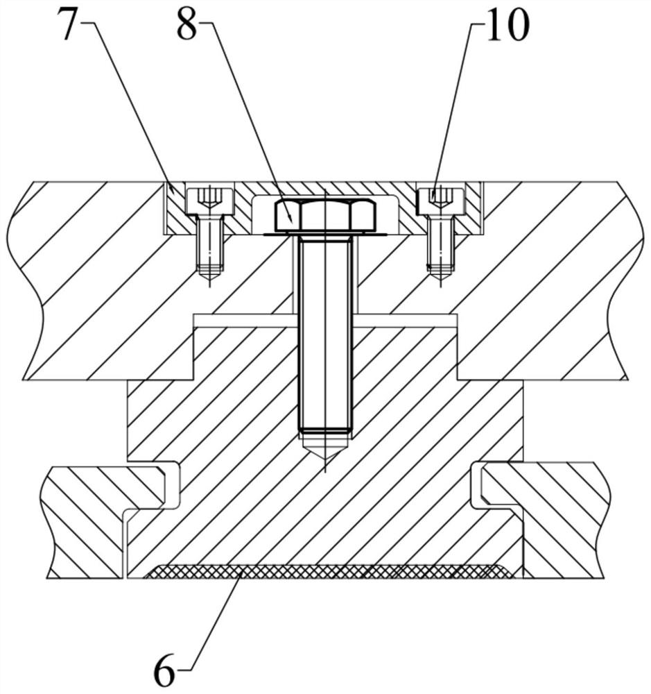
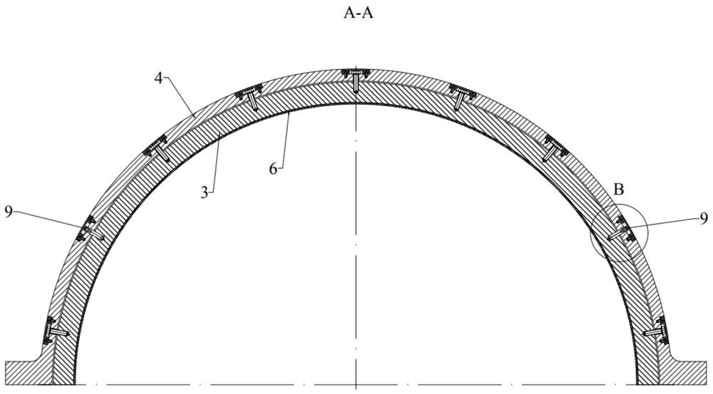
[0037] The following will be combined with Figure 1-4 , the present invention will be further described.

[0038] Such as figure 1 As shown, the detachable tip seal ring of an axial flow compressor includes: a tip seal ring 3, a compressor cylinder 4, an abradable coating 6, and a fixing piece.

[0039] combine image 3 As shown (only half as an example), the tip seal ring 3 is a ring structur...


PUM


Abstract

The invention discloses a detachable blade tip sealing ring of an axial flow compressor and an installation method. The detachable blade tip sealing ring comprises a blade tip sealing ring body, a compressor air cylinder, an abradable coating, and a fixing part. The blade tip sealing ring body is of an annular structure, and convex rings are arranged on the outer ring of the blade tip sealing ringbody; a plurality of annular grooves are formed in the inner surface of the compressor air cylinder; the convex rings are installed in the annular grooves through the fixing part; and the abradable coating is sprayed on the inner wall of the blade tip sealing ring. The detachable blade tip sealing ring of the axial flow compressor and the installation method have the advantages that the abradablecoating is sprayed on the inner wall surface of the blade tip sealing ring, and the radial airflow gap is effectively controlled through the scraping effect of the blade tip of a movable blade on thecoating in the operation process, so that the maximum pressure difference is obtained, and the efficiency of an air compressor is remarkably improved; and the detachable blade tip sealing ring solvesthe technical problems that in the prior art, a coating is directly sprayed to the inner wall of an air cylinder, so that machining is difficult, and deformation is prone to occurring, so that the blade tip sealing ring can be replaced under the condition that a rotor is not moved, and maintenance and updating are convenient.

Description

technical field [0001] The invention relates to the design and manufacture field of an axial flow compressor, in particular to a detachable tip sealing ring of an axial flow compressor and an installation method. Background technique [0002] The research shows that the tip clearance between the compressor motor blade and the inner wall of the compressor cylinder has an important influence on the compressor efficiency. Reducing the blade tip clearance is an effective way to improve the efficiency of the compressor. However, in the design and manufacture of the compressor, there is usually enough margin for the blade tip clearance. The influence of factors such as error, assembly error, displacement and deformation caused by component vibration will cause the gap between the compressor rotor blade and the cylinder to be too small, causing scraping and wear of the rotor blade and cylinder and damage to the rotor blade, and in severe cases, it will cause the compressor to break...

Claims


Application Information

Patent Timeline
IPC IPC(8): F04D29/08F04D29/02F04D29/52F04D29/64B23P15/00B23P19/00
CPCF04D29/083F04D29/023F04D29/526F04D29/644B23P15/00B23P19/00
Inventor 祝华云郑健生隋永枫辛小鹏张宏伟屠瑶詹长庚但汉攀
Owner HANGZHOU TURBINE POWER GRP
Learn More