Supercharge Your Innovation With Domain-Expert AI Agents!

Hydraulic control system of gearbox of engineering vehicle

A technology for hydraulic control systems and engineering vehicles, which can be used in transmission control, components with teeth, non-mechanical drive clutches, etc., and can solve problems such as hidden safety hazards and dangers.

Active Publication Date: 2021-01-01
烟台裕华液力机械有限公司
View PDF7 Cites 1 Cited by
  • Summary
  • Abstract
  • Description
  • Claims
  • Application Information

AI Technical Summary

Problems solved by technology

The above-mentioned machine can cut off the power of the vehicle when the driver steps on the brakes, that is, the hydraulic fluid (pressure oil) cannot reach the forward clutch 13 or the reverse clutch 14, thereby protecting the brakes and transmission devices of the engineering vehicle. However, under special working conditions For example, when a machine (engineering vehicle) is driving on a downhill section, the power is completely cut off when the driver steps on the brakes, which poses a safety hazard. If the engineering vehicle has a large load at this time, its weight is tens of tons, or even more big, very dangerous

Method used


Image

  • Hydraulic control system of gearbox of engineering vehicle

Examples


Embodiment Construction

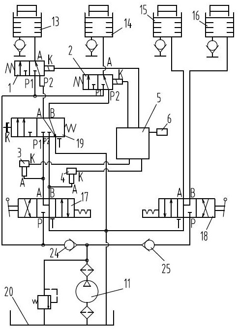
[0010] The present invention will be further described below in conjunction with the accompanying drawings and given embodiments.

[0011] A hydraulic control system for a gearbox of an engineering vehicle, comprising a pump 11, a forward clutch 13, a reverse clutch 14, a first transmission clutch 15, a second transmission clutch 16, a reversing control valve 17, a transmission control valve 18, a brake The cut-off valve 19 and the low-pressure fluid reservoir 20; the oil inlet P of the reversing control valve 17 and the oil inlet P of the speed change control valve 18 are all communicated with the oil outlet of the pump 11; the execution of the speed change control valve 18 The port A and the execution port B communicate with the first transmission clutch 15 and the second transmission clutch 16 respectively. The oil return port T of the reversing control valve 17 , the oil return port T of the transmission control valve 18 and the oil return port T of the brake trip valve 19...


PUM


Abstract

The invention provides a hydraulic control system of a gearbox of an engineering vehicle. The hydraulic control system comprises a pump, a forward clutch, a backward clutch, a first speed change clutch, a second speed change clutch, a reversing control valve, a speed change control valve, a brake gear-breaking valve, a low-pressure fluid storage device, a first electromagnetic valve, a second electromagnetic valve, a first pressure sensor, a second pressure sensor, a main controller and a gradient sensor, wherein the wiring end K of the first electromagnetic valve, the wiring end K of the second electromagnetic valve, the wiring end K of the first pressure sensor, the wiring end K of the second pressure sensor and the gradient sensor are all electrically connected with the main controlleror are in wireless communication connection with the main controller. According to the hydraulic control system, power cannot be cut off when the engineering vehicle brakes when running on a downhillroad section, and power can be cut off when the engineering vehicle brakes when running on other road sections except the downhill road section.

Description

technical field [0001] The invention relates to an engineering vehicle, in particular to a hydraulic control system for a gearbox of an engineering vehicle. Background technique [0002] Chinese patent document CN204164330U (Application No. 201420622099.4) discloses a hydraulic control system for a transmission and a machine including the system. When the machine is in normal operation, the brake trip valve 19 is in the position shown in Figure 2-4 under the action of compressed gas. The ON position shown enables hydraulic fluid to be supplied from the third or fourth port of the reversing control valve 17 to the corresponding forward clutch 13 or reverse clutch 14, so that the machine can be engaged in forward gear or reverse gear. When the brake (braking) operation is applied, the effect of the compressed gas is removed, and the brake disconnect valve 19 is switched to the following position under the action of the compressed spring figure 1 The disengaged position is sho...

Claims


Application Information

Patent Timeline
IPC IPC(8): F16H59/66F16H61/02F16H61/30F16D25/10F16D25/12
CPCF16H59/66F16H61/0267F16H61/0276F16H61/30F16D25/10F16D25/14F16H2059/663
Inventor 常路华
Owner 烟台裕华液力机械有限公司
Features
  • R&D
  • Intellectual Property
  • Life Sciences
  • Materials
  • Tech Scout
  • Unparalleled Data Quality
  • Higher Quality Content
  • 60% Fewer Hallucinations
Learn More