Energy-saving and environment-friendly isolated heat dissipation charging pile

An energy saving, environmental protection, charging pile technology, applied in charging stations, electric vehicle charging technology, electric vehicles, etc., can solve the problems affecting the normal use of charging piles, energy consumption, etc., and achieve the effect of strong adaptability and accelerated heat dissipation efficiency

Inactive Publication Date: 2021-01-05
朱婕妤
View PDF0 Cites 3 Cited by
  • Summary
  • Abstract
  • Description
  • Claims
  • Application Information

AI Technical Summary

Problems solved by technology

[0003] At present, the traditional heat dissipation methods of charging piles are mainly natural cooling (mainly relying on heat sinks), forced air cooling and air conditioning. Due to the influence of factors such as volume, cost, and reliability, most companies currently use forced air cooling. However, the use of forced air cooling will bring interference such as dust, corrosive gas, and moisture, which will affect the normal use of the charging pile and consume a lot of energy.

Method used


Image

  • Energy-saving and environment-friendly isolated heat dissipation charging pile
  • Energy-saving and environment-friendly isolated heat dissipation charging pile
  • Energy-saving and environment-friendly isolated heat dissipation charging pile

Examples


Embodiment 1

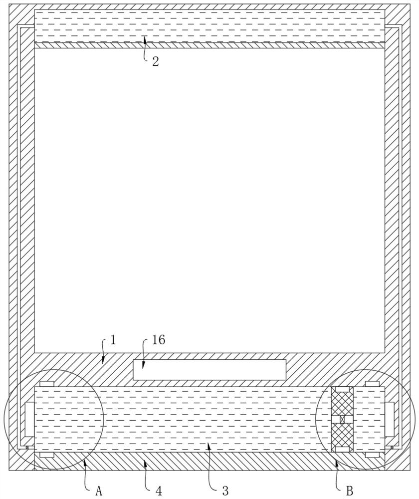
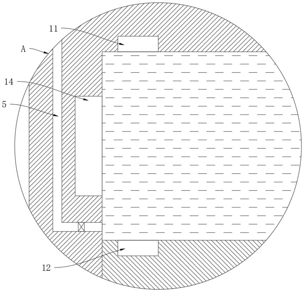
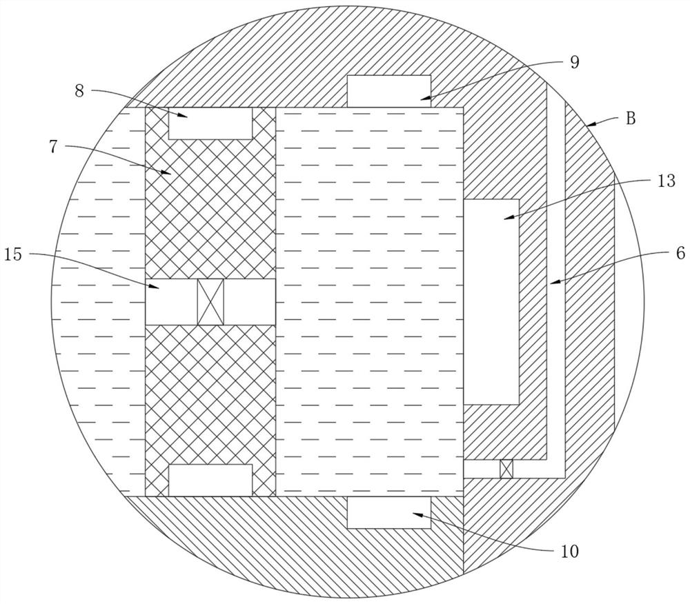
[0024] refer to Figure 1-4 , an energy-saving and environment-friendly isolated heat dissipation charging pile, comprising a hollow charging pile body 1, the inner top wall and the lower end surface of the charging pile body 1 are respectively provided with a heat absorption groove 2 and a cooling groove 3, and the heat absorption groove 2 and the cooling groove The notches of the groove 3 are sealed and fixedly connected with the heat conducting plate 4, the heat-absorbing groove 2 and the cooling groove 3 are filled with cooling liquid, and the cooling groove 3 is vertically sealed and slidingly connected with a magnetic piston 7, and the magnetic piston 7 moves the cooling groove 3. It is divided into a driving area and a driven area. A connecting pipe 15 connecting the driving area and the driven area is provided on the magnetic piston 7. A first one-way valve is installed in the connecting pipe 15. The first one-way valve only allows the driving area to The internal gas ...

Embodiment 2

[0030] refer to Figure 5-6 The difference between this embodiment and Embodiment 1 is that the lower end surface of the heat conduction plate 4 at the lower end surface of the charging pile body 1 is symmetrically provided with placement grooves 17, and each placement groove 17 is installed with a plurality of Fan blades 18, and coil springs are elastically connected between each rotating shaft and the placement groove 17, winding rollers 19 are interference-fitted on the rotating shafts, and traction wires are fixedly connected between both sides of the magnetic piston 7 and the winding rollers 19 , The charging pile body 1 is provided with a slideway for the traction line to slide, and a sealing rubber is provided between the slideway and the traction line, so as to avoid leakage of the coolant in the cooling tank 3 .

[0031]This embodiment can illustrate its functional principle through the following operation mode: when the magnetic piston 7 in the cooling tank 3 moves t...


PUM


Abstract

The invention discloses an energy-saving and environment-friendly isolation type heat dissipation charging pile which comprises a charging pile body with the hollow interior, a heat absorption grooveand a cooling groove are formed in the inner top wall and the lower end face of the charging pile body correspondingly, and heat conduction plates are fixedly connected to groove openings of the heatabsorption groove and the cooling groove in a sealed mode; the heat absorption groove and the cooling groove are both filled with cooling liquid, a magnetic piston is vertically connected into the cooling groove in a sealed and sliding mode, and the cooling groove is divided into a driving area and a driven area through the magnetic piston. Temperature difference inside and outside the charging pile body is used for generating power to drive cooling liquid in the heat absorption groove and the cooling groove to circularly flow to cool the charging pile body, and compared with traditional forced air cooling, the temperature in the charging pile body can be prevented from being too high; meanwhile, input of external energy sources is not needed, energy conservation and environmental protection are achieved, and adaptability is high.

Description

technical field [0001] The invention relates to the technical field of charging piles, in particular to an energy-saving and environment-friendly isolated heat dissipation charging pile. Background technique [0002] New energy vehicles need to be equipped with special charging piles. When charging piles are used, more heat will be generated, and compared with traditional communication power cabinets, it will emit more heat. Taking the 60KW system power as an example, only the modules dissipate heat The amount reaches 60*0.05*1000=3000W, which means that during the charging process of the charging pile, the heat generated is three times that of the communication outdoor cabinet under the same volume condition. [0003] At present, the traditional heat dissipation methods of charging piles are mainly natural cooling (mainly relying on heat sinks), forced air cooling and air conditioning. Due to the influence of factors such as volume, cost, and reliability, most companies cur...

Claims


Application Information

Patent Timeline
Patent Type & Authority Applications(China)
IPC IPC(8): B60L53/302B60L53/31
CPCB60L53/302B60L53/31Y02T10/70Y02T10/7072Y02T90/12
Inventor 朱婕妤
Owner 朱婕妤
Why Eureka
Try Eureka