Eureka AIR delivers breakthrough ideas for toughest innovation challenges, trusted by R&D personnel around the world.

Drying system for kitchen leftover treatment

A technology for kitchen leftovers and drying systems, which is applied in the directions of grain processing, dry goods processing, drying, etc., can solve the problems of increasing the energy consumption of the dryer, slow drying speed and high drying cost, so as to improve the energy consumption. The effect of utilization rate, increasing contact area and improving processing efficiency

Inactive Publication Date: 2021-01-05
深圳市腾浪再生资源发展有限公司
View PDF5 Cites 0 Cited by
  • Summary
  • Abstract
  • Description
  • Claims
  • Application Information

AI Technical Summary

Problems solved by technology

The composition of kitchen residues is complex, generally including various substances such as oil and water, fruit peels, vegetables, rice noodles, meat, etc., and kitchen residues often need to be dehydrated and dried during the processing process, and the existing drying equipment is used during the process of use There are often the following problems: 1. The existing drying equipment has a single function, can only perform simple drying operations, and cannot dehydrate the processed residues in time, and the existing dehydration equipment is often set separately from the drying equipment 2. The existing drying equipment often has a slow drying speed during the drying process, resulting in low efficiency in the treatment of the entire kitchen residue; 3. The existing drying equipment Drying equipment often uses hot air to dry kitchen leftovers, and the dried hot air is accompanied by a large amount of heat waste during the discharge process, which increases the energy consumption of the dryer, high drying costs, and reduced energy utilization.

Method used


Image

  • Drying system for kitchen leftover treatment
  • Drying system for kitchen leftover treatment
  • Drying system for kitchen leftover treatment

Examples


Embodiment Construction

[0025] In order to make the technical means, creative features, goals and effects achieved by the present invention easy to understand, the present invention will be further described below in conjunction with specific embodiments.

[0026] In the description of the present invention, it should be noted that the terms "upper", "lower", "inner", "outer", "front end", "rear end", "both ends", "one end", "another end" The orientation or positional relationship indicated by etc. is based on the orientation or positional relationship shown in the drawings, and is only for the convenience of describing the present invention and simplifying the description, rather than indicating or implying that the referred device or element must have a specific orientation, use a specific Azimuth configuration and operation, therefore, should not be construed as limiting the invention. In addition, the terms "first" and "second" are used for descriptive purposes only, and should not be understood ...


PUM


Abstract

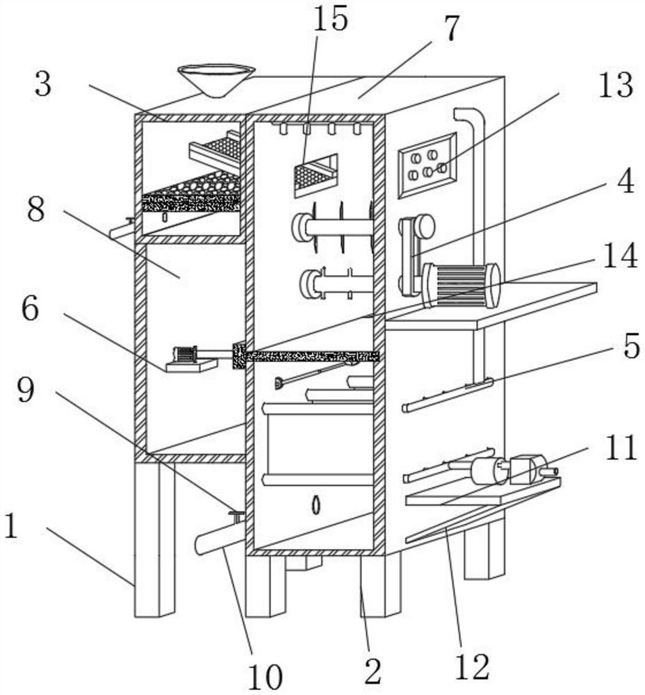
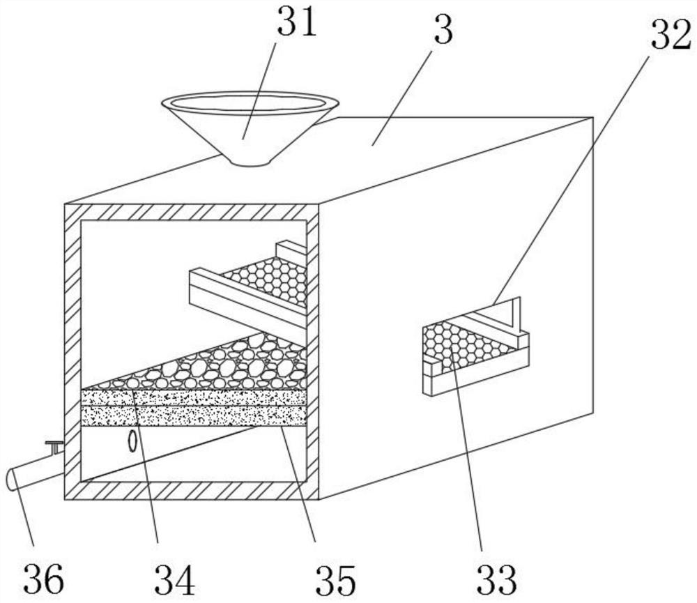
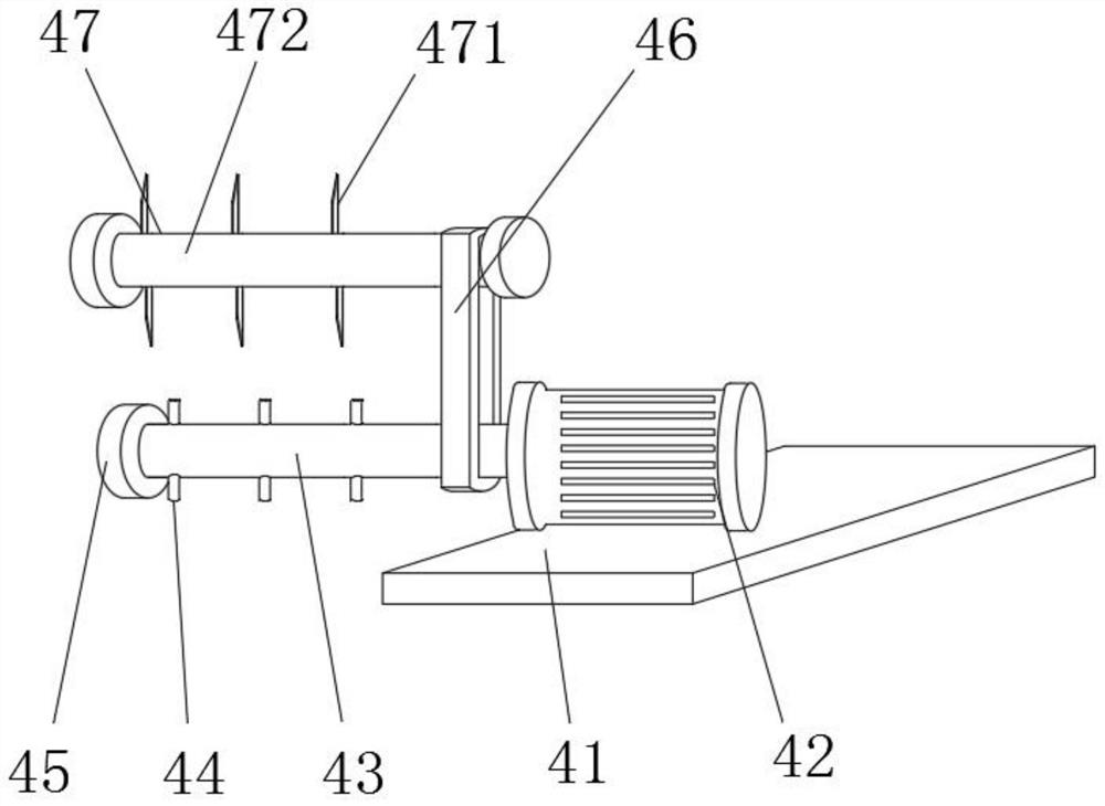
The invention discloses a drying system for kitchen leftover treatment. The drying system involves a machine box, wherein a dehydration box is fixedly arranged on the upper side of the left end of themachine box, a mounting box is fixedly arranged at the lower end of the dehydration box, and a control face board and a stirring device are fixedly arranged on the upper portion of the right end of the machine box correspondingly; and a switch piece is fixedly arranged in the middle portion of the left end of the mounting box, and a drying device is fixedly arranged at the right end of the machine box. According to the drying system for kitchen leftover treatment, the dehydration box is arranged at the upper end of the mounting box so that the occupied area of equipment can be reduced while the drying system has dehydration performance, and the equipment is convenient to use; the stirring device can be used for crushing treated materials while the contact area between the materials and hot air is increased, so that the drying speed is increased; and in addition, after drying air is introduced into drying pieces for heat exchange, the hot air can be continuously introduced into guide pipes two through a guide pipe one and finally discharged through discharging pipes, so that the hot air is reutilized, then the energy utilization rate is increased, and the drying cost is reduced.

Description

technical field [0001] The invention relates to the technical field of kitchen residue treatment, in particular to a drying system for kitchen residue treatment. Background technique [0002] Kitchen leftovers refer to food residues, food processing waste, etc. produced by units such as canteens and restaurants. The composition of kitchen residues is complex, generally including various substances such as oil and water, fruit peels, vegetables, rice noodles, meat, etc., and kitchen residues often need to be dehydrated and dried during the processing process, and the existing drying equipment is used during the process of use There are often the following problems: 1. The existing drying equipment has a single function, can only perform simple drying operations, and cannot dehydrate the processed residues in time, and the existing dehydration equipment is often set separately from the drying equipment 2. The existing drying equipment often has a slow drying speed during the ...

Claims


Application Information

Patent Timeline
Patent Type & Authority Applications(China)
IPC IPC(8): F26B11/16F26B21/00F26B25/00F26B25/04B02C18/06B02C18/18C02F9/02
CPCF26B11/16F26B25/04F26B25/002F26B21/004C02F9/00B02C18/06B02C18/18F26B2200/04
Inventor 张琦吴伟浩吴双文包自立
Owner 深圳市腾浪再生资源发展有限公司
Why Eureka
Eureka Blog
Learn More