Effective magnetic potential calculation method for permanent magnet magnetic coupler

A magnetic coupling and calculation method technology, applied in the direction of permanent magnetic clutch/brake, electric brake/clutch, design optimization/simulation, etc., can solve the application constraints of rapid optimization, and the effective magnetic potential of permanent magnetic coupling cannot be quantified Given calculation results, long calculation time and other problems, to achieve rapid and accurate calculation and prediction, simple and effective calculation method, and simple calculation process

Active Publication Date: 2021-01-05
DALIAN UNIV OF TECH
View PDF5 Cites 4 Cited by
  • Summary
  • Abstract
  • Description
  • Claims
  • Application Information

AI Technical Summary

Problems solved by technology

The calculation method of the effective magnetic potential of the permanent magnet magnetic coupler mainly adopts the finite element analysis method. The calculation result of the finite element analysis method is accurate, the precision is high, and the fine solution can be realized, but it requires a complicated modeling process and consumes a lot of time and resources. The application of rapid optimization in actual engineering is greatly restricted
[0003] For the calculation of the effective magnetic potential of the permanent magnet magnetic coupler, Meng Xiangrui of Harbin Institute of Technology published a dissertation on June 1, 2014 "Research on the Axial Flux Adjustable Permanent Magnetic Coupler". Established a three-dimensional model of the structure of the coupler, analyzed the influence of magnetic flux leakage by using the finite element analysis method, and qualitatively analyzed the trend of the effective magnetic potential of the permanent magnet magnetic force coupler affected by the air gap, but the modeling process is complicated, and for the permanent magnet magnetic force The effective magnetic potential of the coupler cannot be calculated quantitatively, the calculation time is lengthy, the requirements for computer hardware are high, and the efficiency is low

Method used


Image

  • Effective magnetic potential calculation method for permanent magnet magnetic coupler
  • Effective magnetic potential calculation method for permanent magnet magnetic coupler
  • Effective magnetic potential calculation method for permanent magnet magnetic coupler

Examples


Embodiment Construction

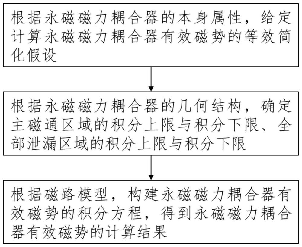
[0039] The present invention will be further described in detail below in conjunction with the accompanying drawings and technical solutions.

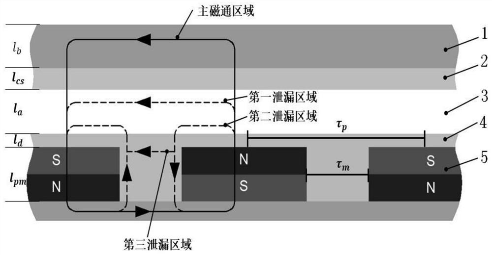
[0040] In this embodiment, the transmission torque of a permanent magnet magnetic coupling with an input speed of 1500 r / min and a single-disc structure with 6 magnetic pole pairs is selected for calculation. Among them, the basic size of the permanent magnet magnetic coupler with an input speed of 1500r / min and a single-disc structure with 6 pole pairs is: the magnetic induction of the permanent magnet H pm =890×10 3 A / m, permanent magnet thickness l pm =25mm, permanent magnet width w pm =50mm, conductor back iron thickness l b =10mm, vacuum permeability μ 0 =4π×10 -7 H / m, conductor rotor thickness l cs =6mm, air gap thickness l a =5mm, permanent magnet rotor thickness l d =1mm, the distance between the centers of adjacent permanent magnets τ p =78.5mm, distance between adjacent permanent magnets τ m =28.5mm

[0041] attach...


PUM


Abstract

The invention discloses an effective magnetic potential calculation method for a permanent magnet magnetic coupler, belongs to the technical field of permanent magnet magnetic transmission, and relates to the effective magnetic potential calculation method for the permanent magnet magnetic coupler. The method comprises the following steps: firstly, giving an equivalent simplified hypothesis for calculating the effective magnetic potential of the permanent magnet magnetic coupler according to the attribute of the permanent magnet magnetic coupler; then, according to the geometric structure of the permanent magnetic coupler, establishing a magnetic circuit model comprising a main magnetic flux region, a first leakage region, a second leakage region and a third leakage region, and determiningan integral upper limit and an integral lower limit of the main magnetic flux region and an integral upper limit and an integral lower limit of each leakage region; and finally, constructing an integral equation of the effective magnetic potential of the permanent magnet magnetic coupler according to the magnetic circuit model to obtain a calculation result of the effective magnetic potential ofthe permanent magnet magnetic coupler. The method is a calculation method with practical engineering popularization and application values, and the calculation method is simple, effective, high in efficiency and short in consumed time.

Description

technical field [0001] The invention belongs to the technical field of permanent magnet magnetic force transmission and relates to a method for calculating the effective magnetic potential of a permanent magnet magnetic force coupler. Background technique [0002] In the traditional transmission system, the motor end and the load end are usually connected by a coupling, but the installation requirements of the coupling are high, and overload protection cannot be realized, which has been unable to meet the development needs of the transmission system of engineering equipment. The permanent magnet magnetic coupling utilizes Faraday's electromagnetic induction principle to achieve effective transmission of torque from the motor end to the load end through the non-contact magnetic force generated between the conductor rotor and the permanent magnet rotor. Compared with the existing couplings, the permanent magnet magnetic coupling has the advantages of high reliability, overload...

Claims


Application Information

Patent Timeline
IPC IPC(8): G06F30/20H02K15/00H02K49/10
CPCG06F30/20H02K15/0006H02K49/106
Inventor 刘巍程习康谭子亮周志龙王文琪于斌超罗唯奇张洋
Owner DALIAN UNIV OF TECH
Why Eureka
Try Eureka