
Panoramic head positioning method, panoramic head positioning system and operation method of panoramic head positioning system

A positioning method and positioning system technology, applied in computer components, image data processing, complex mathematical operations, etc., can solve problems such as imaging failure and missing areas

Active Publication Date: 2021-01-05
SHANGHAI UEG MEDICAL IMAGING EQUIP CO LTD
View PDF5 Cites 1 Cited by
  • Summary
  • Abstract
  • Description
  • Claims
  • Application Information

AI Technical Summary

Problems solved by technology

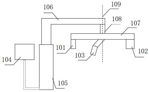
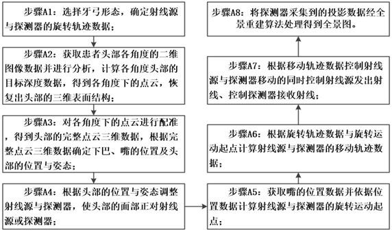
[0003] The technical problem to be solved by the present invention is that the existing scheme requires manual judgment to locate the patient, which has certain requirements for the operator. If the judgment is wrong, it will easily lead to the failure of imaging and shooting; supporting structures such as jaw rest and mouthpiece will also block the face, causing Part of the area is missing during facial scanning. The present invention provides a panoramic head positioning method. The three-dimensional surface structure of the head is obtained through structured light three-dimensional surface reconstruction technology, and important anatomical structures such as the jaw and mouth of the head and face are identified, and these anatomical structures are used position, calculate the position and posture of the head, realize head positioning, and use it as a position reference for panoramic imaging; this method does not require jaw rests, mouthpieces, laser lights, etc., which not only eliminates the process of manual judgment, but also reduces operation Complexity, reducing user learning costs, and eliminating the use of relevant disposable protective sleeves, reducing additional waste, to solve the defects caused by existing technologies

Method used


Image

  • Panoramic head positioning method, panoramic head positioning system and operation method of panoramic head positioning system
  • Panoramic head positioning method, panoramic head positioning system and operation method of panoramic head positioning system
  • Panoramic head positioning method, panoramic head positioning system and operation method of panoramic head positioning system

Examples


Embodiment Construction

[0072] In order to make the technical means, creative features, goals and effects achieved by the invention easy to understand, the technical solutions in the embodiments of the present invention are clearly and completely described below in conjunction with specific illustrations. Obviously, the described embodiments are the embodiment of the present invention. Some examples, but not all examples.

[0073] Based on the embodiments of the present invention, all other embodiments obtained by persons of ordinary skill in the art without making creative efforts belong to the protection scope of the present invention.

[0074] It should be noted that the structures, proportions, sizes, etc. shown in the drawings attached to this specification are only used to match the content disclosed in the specification, for those who are familiar with this technology to understand and read, and are not used to limit the implementation of the present invention. Limiting conditions, so there is...


PUM


Abstract

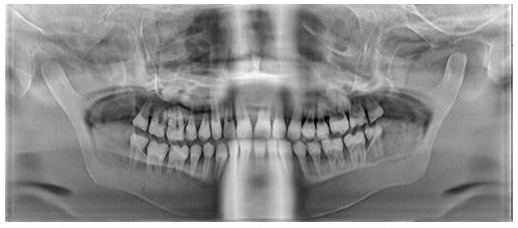
The invention discloses a panoramic head positioning method, a panoramic head positioning system and an operation method of the panoramic head positioning system. The positioning method comprises thefollowing steps: selecting a dental arch form to determine rotation track data; acquiring and analyzing two-dimensional image data of the head of the patient at each angle, calculating to obtain target depth data and point cloud at each angle, and recovering a three-dimensional surface structure of the head; registering the point cloud at each angle to obtain complete point cloud three-dimensionaldata, and determining the positions of the jaw and the mouth and the position and posture of the head; adjusting the radiation source and the detector according to the position and posture of the head to enable the face of the head to directly face the radiation source or the detector; acquiring position data of the nozzle and calculating a rotary motion starting point of the ray source and the detector; calculating moving track data according to the rotating track data and the rotating motion starting point; controlling the ray source to emit rays while controlling the ray source and the detector to move according to the movement track data, and controlling the detector to receive the rays; and processing the projection data acquired by the detector through a panoramic reconstruction algorithm to obtain a panoramic image.

Description

technical field [0001] The invention relates to the field of panoramic head positioning, in particular to a panoramic head positioning method, a positioning system and an operating method thereof. Background technique [0002] In dental CBCT, the head needs to be positioned before panoramic scanning to obtain an accurate image; traditional methods usually use the jaw rest and mouthpiece to determine the position of the jaw and teeth, and use laser light to assist to determine the angle of the patient's head. This method requires manual judgment to locate the patient, which has certain requirements for the operator. If the judgment is wrong, it will easily lead to the failure of imaging and shooting; supporting structures such as jaw rest and mouthpiece will also block the face, resulting in the loss of some areas during facial scanning; each patient Relevant disposable protective sleeves need to be replaced before positioning, resulting in waste. Contents of the invention ...

Claims


Application Information

Patent Timeline
IPC IPC(8): G06K9/00G06T7/00G06T7/593G06T7/70G06F17/11
CPCG06T7/0012G06T7/593G06T7/70G06F17/11G06T2207/30036G06V20/653G06V40/161
Inventor 邓露珍陈毅张丽灵高丰伟王晨学杨旭明
Owner SHANGHAI UEG MEDICAL IMAGING EQUIP CO LTD
Learn More