A rotary piezoelectric-friction composite generator

A generator, rotary technology, applied in the direction of friction generator, generator/motor, piezoelectric effect/electrostrictive or magnetostrictive motor, etc., can solve the problem of low vibration frequency and rotating body speed adaptability, sliding The problems of friction and wear between the friction pairs of the triboelectric generator, low power generation capacity and low energy density per unit volume, etc., achieve the effect of simple structure and excitation process, strong adaptability of rotation speed, and avoiding surface friction and wear

Active Publication Date: 2021-10-15
ZHEJIANG NORMAL UNIVERSITY
View PDF0 Cites 0 Cited by
  • Summary
  • Abstract
  • Description
  • Claims
  • Application Information

AI Technical Summary

Problems solved by technology

From the perspective of practical application, various types of generators currently proposed still face many technical bottlenecks. The common problems are summarized as follows: ① low power generation capacity and energy density per unit volume; Low adaptability to flow velocity, vibration frequency and rotating body speed, ③low reliability, such as piezoelectric ceramics are easily damaged due to excessive environmental vibration intensity, and sliding friction generators are easy to fail due to friction and wear between friction pairs. ④There is electromagnetic interference , such as electromagnetic generators, nonlinear piezoelectric and friction generators based on magnetic coupling auxiliary excitation, there is a certain magnetic field when they work
Of course, it is still difficult to solve all the above-mentioned problems in the same generator
The common feature of pure piezoelectric generators and friction generators is that they have no electromagnetic interference, so they are more suitable for wireless sensor monitoring systems, and their respective power generation capabilities, reliability and environmental adaptability need to be further improved

Method used


Image

  • A rotary piezoelectric-friction composite generator
  • A rotary piezoelectric-friction composite generator
  • A rotary piezoelectric-friction composite generator

Examples


Embodiment Construction

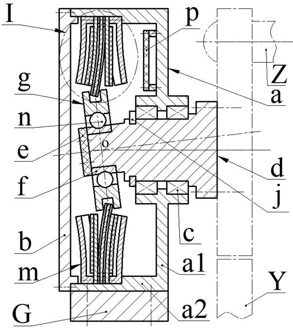
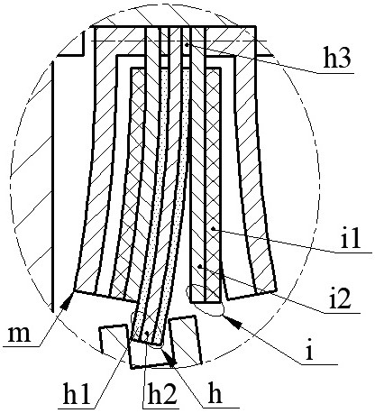
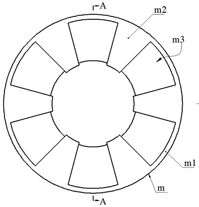
[0023] The composite generator proposed by the present invention mainly includes casing a, bearing c, end cover b, rotating shaft d, fixed ring f, excitation ring g, rolling element n, composite beam h, piezoelectric vibrator i, ring frame m and circuit Board p.

[0024] The end cover b is installed on the end of the casing a2 of the casing a through screws. The rotating shaft d is composed of a flange d1, a flat shaft d2 and an inclined shaft d3. One end of the flat shaft d2 of the rotating shaft d is provided with a flange d1, and the other end is provided with a There is an inclined shaft d3, a flat shaft d2 is installed on the shell bottom a1 of the casing a through a circlip j and a bearing c, a fixed ring f is installed on the inclined shaft d3 through a retainer e and screws; the excitation ring g is installed through rolling elements n sets On the fixed ring f, the rolling element n is a ball or a cylinder, and the flat axis x1 and the oblique axis x2 have an axial inc...


PUM


Abstract

The invention relates to a rotary piezoelectric-friction composite generator, which belongs to the technical field of new energy. The end of the flat shaft of the rotating shaft is provided with an inclined shaft, the flat shaft is installed on the bottom of the casing, and the excitation ring with a pull-out groove on the outer edge is set on the inclined shaft; The piezoelectric vibrator is located on both sides of the composite beam, the ring frame ring plate is clamped on the outside of the piezoelectric vibrator, and the guard plate of the ring frame is provided with a sinker; the composite beam is composed of the beam base plate and the friction layer on both sides, and the piezoelectric vibrator is composed of the vibrator The substrate is composed of a piezoelectric sheet bonded to one side, the vibrator substrate is installed close to the friction layer of the composite beam, the piezoelectric sheet is installed close to the ring frame and placed in the sink, and the free end of the composite beam is placed in the pull groove; the vibrator substrate and The piezoelectric sheet constitutes the piezoelectric power generation unit, the vibrator substrate and the composite beam constitute the friction power generation unit, and the excitation ring drives the composite beam to swing axially to make the piezoelectric vibrator bend and deform, and the vibrator substrate and the friction layer alternately contact and separate, and then convert the mechanical energy into electrical energy.

Description

technical field [0001] The invention belongs to the technical field of new energy and energy recovery, and specifically relates to a rotary piezoelectric-friction composite generator, which is used for collecting kinetic energy of rotating shafts such as wind energy, water flow, and wind power generators. Background technique [0002] In recent years, real-time health sensing monitoring technology for high-rise buildings, bridges, large and high-speed rotating machinery has been widely used. In addition, the monitoring of river water quality pollution, flood prevention and early warning, and air pollution has been highly valued by relevant state departments. Domestic experts and scholars have successively proposed corresponding monitoring methods and means, such as water quality monitoring technology for river water pollution, flood control Monitoring technologies such as rainfall, water level, and river water velocity for natural disasters such as landslides and mudslides. ...

Claims


Application Information

Patent Timeline
Patent Type & Authority Patents(China)
IPC IPC(8): H02N2/18H02N1/04
CPCH02N1/04H02N2/185H02N2/186
Inventor 阚君武吴亚奇文一杰张李林声弟王淑云吴鸣程光明
Owner ZHEJIANG NORMAL UNIVERSITY
Why Eureka
Try Eureka