
Case heat dissipation structure of helicopter airborne equipment

A technology of airborne equipment and heat dissipation structure, which is applied to the structural parts of electrical equipment, cooling/ventilation/heating transformation, electrical components, etc. problems, to meet the requirements of electromagnetic compatibility, high heat dissipation efficiency, and high reliability

Pending Publication Date: 2021-01-05
北京中科国达科技有限公司
View PDF0 Cites 0 Cited by
  • Summary
  • Abstract
  • Description
  • Claims
  • Application Information

AI Technical Summary

Problems solved by technology

The heat dissipation efficiency of the air-cooled heat dissipation method is moderate, and it is suitable for equipment that does not require high heat dissipation, but the electromagnetic compatibility of the air-cooled heat dissipation method is poor
The liquid cooling method can obtain the highest heat dissipation efficiency, but requires secondary cooling equipment, which will increase the weight by hundreds of kilograms, and is not suitable for use on helicopters
The conduction cooling method has good electromagnetic compatibility, but the heat dissipation efficiency is low, and it is generally used for low power consumption devices (below 50 watts)
For the heat dissipation problem of helicopter airborne equipment with high power consumption (above 50 watts), the current three heat dissipation methods cannot be solved well.

Method used


Image

  • Case heat dissipation structure of helicopter airborne equipment
  • Case heat dissipation structure of helicopter airborne equipment
  • Case heat dissipation structure of helicopter airborne equipment

Examples


Embodiment Construction

[0031] In order to make the objectives, technical solutions and advantages of the present invention clearer, the technical solutions in the embodiments of the present invention will be described in more detail below in conjunction with the drawings in the embodiments of the present invention. In the drawings, the same or similar reference numerals denote the same or similar elements or elements having the same or similar functions throughout. The described embodiments are some, but not all, embodiments of the invention. The embodiments and directional words described below by referring to the figures are exemplary and are intended to explain the present invention, but should not be construed as limiting the present invention. Based on the embodiments of the present invention, all other embodiments obtained by persons of ordinary skill in the art without creative efforts fall within the protection scope of the present invention. Embodiments of the present invention will be des...


PUM

PropertyMeasurementUnit
Diameteraaaaaaaaaa
Widthaaaaaaaaaa
Thicknessaaaaaaaaaa

Abstract

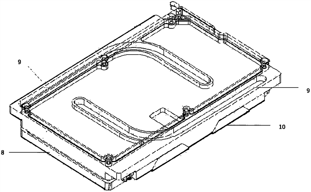
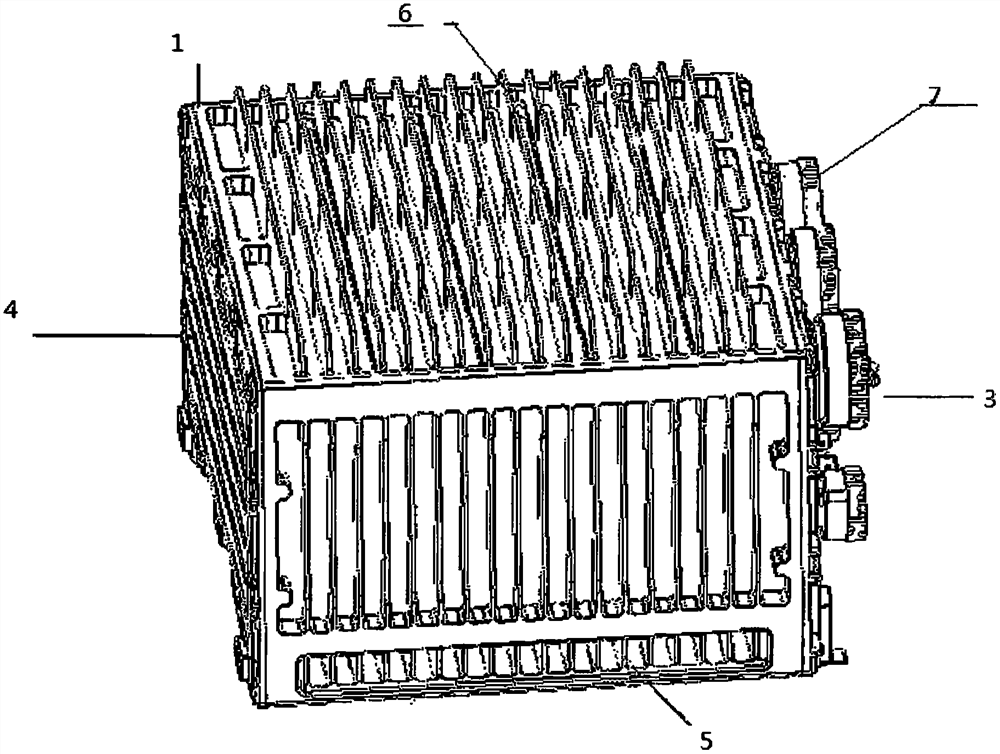
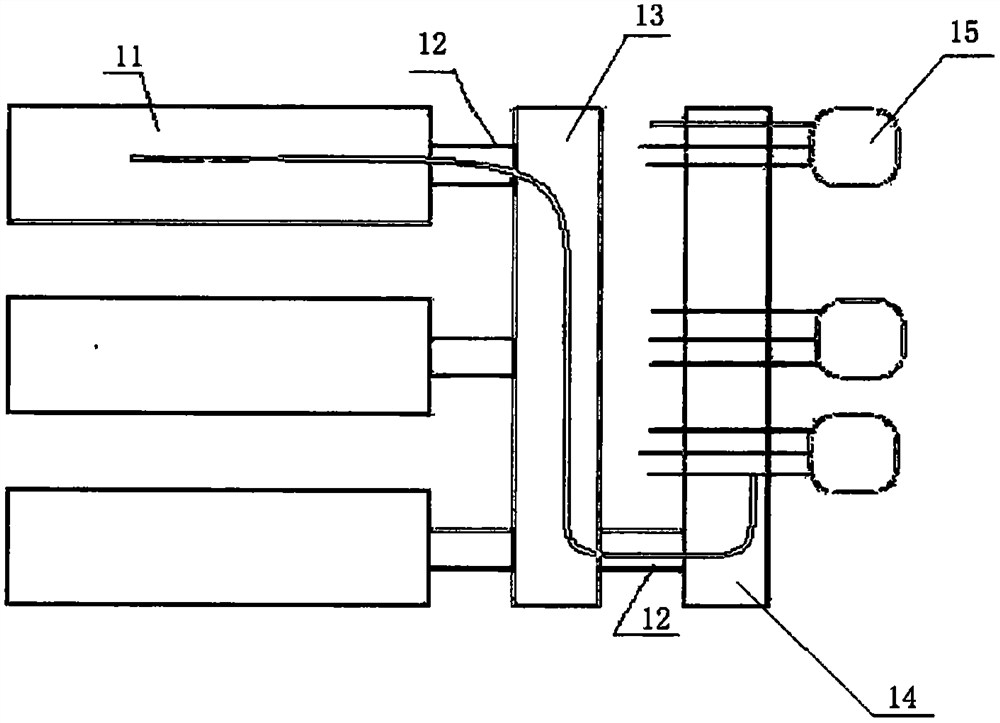
The invention provides a case heat dissipation structure of helicopter airborne equipment. The structure comprises a case main body, a processing module, a VPX or CPCI connector, a PCB mother board, aPCB interface board and an aviation connector; the structure further comprises a heat dissipation cold plate and L-shaped heat pipes; a top panel and a bottom panel of the case main body form a mainheat dissipation surface; two side panels are chip mounting surfaces; the heat dissipation cold plate is mounted on the top panel and the bottom panel of the case main body through lockers; l-shaped heat conduction grooves are formed in the heat dissipation cold plate; the section of each heat conduction groove is in a U shape; the heat dissipation cold plate is tightly connected with the processing module and used for dissipating heat of the processing module; the L-shaped heat pipes are arranged in the heat conduction grooves and cover the processing module through heat conduction pads and extend to the mounting surface of the heat dissipation cold plate and a case. With the case heat dissipation structure of helicopter airborne equipment of the invention, chip heat is directly conductedto the case main body through the heat pipes, thermal resistance and conduction paths are reduced, and the requirements for onboard environment adaptability and electromagnetic compatibility can be met.

Description

technical field [0001] The invention relates to the field of temperature control of electronic equipment, in particular to a chassis heat dissipation structure of helicopter airborne equipment. Background technique [0002] With the continuous development of electronic technology, the power of electronic equipment systems is getting larger and larger, but the physical size is getting smaller and smaller, the heat flux density increases sharply, and the risk of heat dissipation increases. Especially in high temperature and severe working environment, good heat dissipation can ensure the reliability of the equipment. The above-mentioned phenomenon is particularly obvious in the field of electronic equipment in the aircraft field, especially in the field of helicopter airborne equipment. At the same time, helicopter airborne equipment also has high requirements for environmental adaptability and weight indicators. [0003] At present, there are three main heat dissipation met...

Claims


Application Information

Patent Timeline
IPC IPC(8): H05K7/20
CPCH05K7/20854
Inventor 张婉滢何浩张孝田张磊叶宗见季长红
Owner 北京中科国达科技有限公司
Learn More