A mining crawler intelligent inspection robot system
A robot system and intelligent inspection technology, applied in crawler vehicles, instruments, motor vehicles, etc., can solve problems such as affecting the layout of the mine, unable to work, wasting time, etc., to achieve small size and weight restrictions, and improved endurance. , the effect of reducing production costs
- Summary
- Abstract
- Description
- Claims
- Application Information
AI Technical Summary
Problems solved by technology
Method used
Image
Examples
Embodiment 1
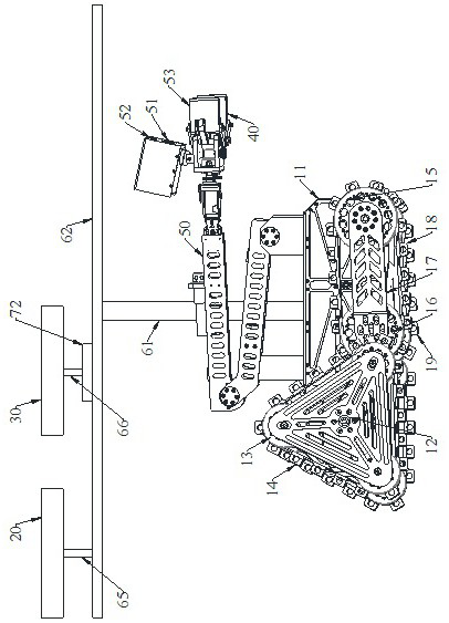
[0044] Such as figure 1 As shown, the mine crawler-type intelligent inspection robot system includes an obstacle-crossing robot and an inspection mechanism, and the obstacle-crossing robot includes a car body 11 and two groups of crawler-type walking mechanisms, and the two groups of crawler-type walking mechanisms are symmetrically arranged on On both sides of the car body 11, the crawler-type traveling mechanism includes a waist-shaped main crawler device, a triangular crawler device located at one end of the main crawler device, and a swing arm device located at the other end of the main crawler device. The main crawler device includes a first Driving wheel, the first driven wheel, the first track 19, the first driving wheel and the first driven wheel are all arranged in the inside of the first track 19, and the first driving wheel cooperates with the first driven wheel to drive the first track 19 Walking; the triangular crawler device includes a second driving wheel 12, th...
Embodiment 2
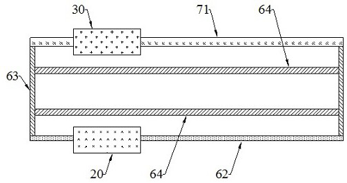
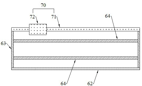
[0051] Based on Example 1, such as Figure 1-3 As shown, the top of the vehicle body 11 is provided with a bracket for fixing the static wind speed measuring tube 20, and a linear motion mechanism for driving the dynamic wind speed measuring tube 30 to perform reciprocating linear motion is installed between the dynamic wind speed measuring tube 30 and the bracket. 70, the dynamic wind speed measuring tube 30 and the static wind speed measuring tube 20 are arranged in relative motion, the linear motion mechanism 70 includes a linear motor guide rail 71, a slide plate 72 matched with the linear motor guide rail 71, and the bracket includes a Linear motor guide rail 71 is the straight bar 62 that is arranged in parallel, two first connecting rods 63 that are respectively arranged on the two ends of linear motor guide rail 71, the second connecting rod 64 that is arranged between two first connecting rods 63, is arranged on the second connecting rod. The third connecting rod 61 b...
Embodiment 3
[0054] Based on Example 2, such as Figure 4 As shown, the static wind speed measuring tube 20 includes a round tubular first pipe body 21, a round rod-shaped second wind speed sensor 22 installed inside the first pipe body 21, and the second wind speed sensor 22 is connected to the first pipe body 21. Coaxial arrangement, a sixth connecting rod 23 is arranged between the second wind speed sensor 22 and the tail end of the first pipe body 21, one end of the sixth connecting rod 23 is fixedly connected with the second wind speed sensor 22, the The other end of the sixth connecting rod 23 is fixedly connected with the tail end of the first tube body 21 .
[0055] The static wind speed measuring tube 20 with this structure can be used to measure the wind speed passing through the inside of the first tube body 21 .
PUM
 Abstract
Description
Claims
Application Information
 - R&D
- Intellectual Property
- Life Sciences
- Materials
- Tech Scout
- Unparalleled Data Quality
- Higher Quality Content
- 60% Fewer Hallucinations
Browse by: Latest US Patents, China's latest patents, Technical Efficacy Thesaurus, Application Domain, Technology Topic, Popular Technical Reports.
© 2025 PatSnap. All rights reserved.Legal|Privacy policy|Modern Slavery Act Transparency Statement|Sitemap|About US| Contact US: help@patsnap.com


