Drying and automatic threading device for earthworm processing
An automatic wear and earthworm technology, applied in drying, food processing, application and other directions, can solve the problems of workers' iron wire scratches, slow drying speed, hidden dangers and other problems, and achieve the effect of reducing labor intensity and improving speed.
- Summary
- Abstract
- Description
- Claims
- Application Information
AI Technical Summary
Problems solved by technology
Method used
Image
Examples
Embodiment 1
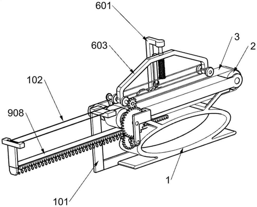
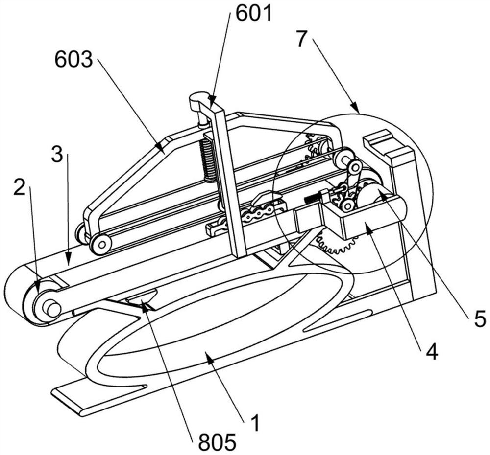
[0024] A drying automatic threading device for earthworm processing, such as Figure 1-8 As shown, it includes a support 1, a support bracket 101, an iron wire 102, a transmission wheel 2, a conveyor belt 3, a mounting plate 4, a driving motor 5, a pressing mechanism 6 and a transmission mechanism 7, and the support bracket 101 is fixedly installed. On one side of the bottom of the support 1, two parallel iron wires 102 are movably placed on the support bracket 101, and the two iron wires 102 are used for threading processing of earthworms, and the two ends of the support 1 are rotated respectively. A transmission wheel-2 is installed, and a transmission belt-3 for placing earthworms and driving its transmission is connected between the two transmission wheels-2, and the mounting plate 4 is fixedly installed on a side of the support 1 top and is connected with the supporting bracket 101 Approaching, the drive motor 5 is fixedly installed on one side of the mounting plate 4 and...
Embodiment 2
[0029] On the basis of Example 1, such as figure 2 and Figure 5 As shown, it also includes a lifting mechanism for assisting the upward lifting of the arc frame 603. The lifting mechanism is installed on the support 1 and the arc frame 603. The lifting mechanism includes a connecting frame 801, a roller 802, and a fixing seat 803. , supporting rollers 804 and bumps 805, the connecting frame 801 is fixedly installed on one side of the arc frame 603 and is close to the fixed frame 601, and the roller 802 is rotatably installed on the lower end of the connecting frame 801 and is close to the conveyor belt 13 , the fixed seat 803 is fixedly installed on the upper side of the support 1 and is close to the fixed frame 601, five support rollers 804 are rotatably installed on the fixed seat 803, and two bumps are fixedly installed on the conveyor belt 3 805 and the protruding block 805 can be in contact with the roller 802 and the support roller 804, and the cooperation between the...
Embodiment 3
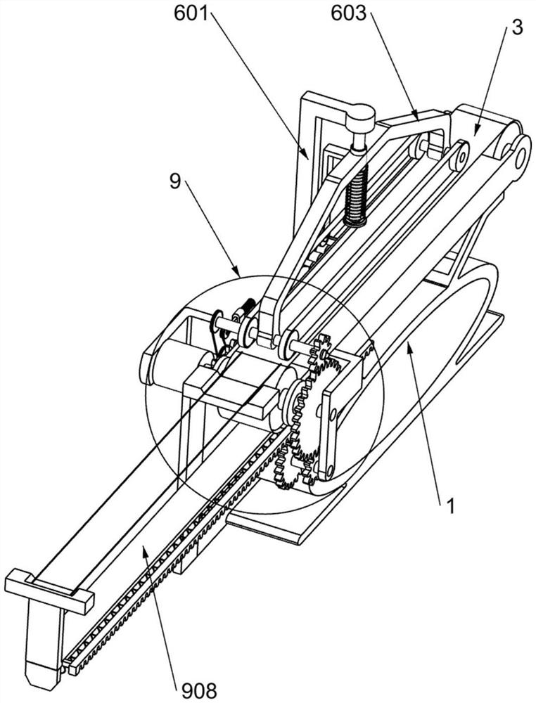
[0032] On the basis of Embodiment 2, it also includes a push mechanism 9 for automatically pushing two iron wires 102 to move to the right to perform threading operations on earthworms. The push mechanism 9 is installed on the support 1 and one of the movable shafts 604 Above, the push mechanism 9 includes a pinion 901, a mounting bracket 902, a large gear 903, a movable shaft 3 904, a connecting gear 905, a transmission gear 906, a sliding sleeve 907, a sliding plate 908, a return spring 909 and a rack 910, so that The pinion 901 is fixedly installed on one of the movable shafts 604 away from the end of the pulley 701, the mounting bracket 902 is fixedly installed on one side of the support 1 and is close to the other transmission wheel 2, and the large gear 903 is installed on one side of the mounting frame 902 through a bearing and a rotating shaft and meshes with the pinion 901, the movable shaft three 904 is mounted on the lower end of the mounting frame 902 through a bear...
PUM
 Abstract
Description
Claims
Application Information
 - R&D
- Intellectual Property
- Life Sciences
- Materials
- Tech Scout
- Unparalleled Data Quality
- Higher Quality Content
- 60% Fewer Hallucinations
Browse by: Latest US Patents, China's latest patents, Technical Efficacy Thesaurus, Application Domain, Technology Topic, Popular Technical Reports.
© 2025 PatSnap. All rights reserved.Legal|Privacy policy|Modern Slavery Act Transparency Statement|Sitemap|About US| Contact US: help@patsnap.com


