Projection screen and projection system
A technology of projection screen and cylindrical microlens, which is applied in the field of projection display, can solve the problems of uneven image intensity and uneven distribution of light intensity displayed on the projection screen, and achieve the effect of improving the uniform effect of display brightness
- Summary
- Abstract
- Description
- Claims
- Application Information
AI Technical Summary
Problems solved by technology
Method used
Image

Examples
Embodiment 1
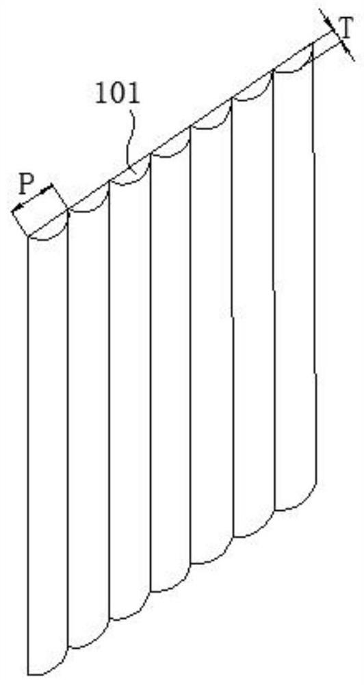
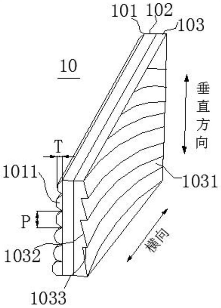
[0047] refer to figure 2 As shown, a projection screen of the present invention includes a columnar microlens layer 101, a first substrate layer 102, and a reflective microstructure layer 103 arranged along the thickness direction of the projection screen, and the columnar microlens layer 101 is arranged on the first substrate layer On one side of 102, the columnar microlens layer 101 includes several columnar microlenses 1011 arranged laterally, and the aspect ratio of the columnar microlenses 1011 gradually decreases from one side to the other along the vertical direction of the projection screen 10, marked as columnar microlenses 1011 The height of the columnar microlens 1011 is T, and the width of the columnar microlens 1011 is P, then the aspect ratio of the columnar microlens 1011 is the ratio of the height of the columnar microlens 1011 to the width of the columnar microlens 1011, that is, the ratio of the columnar microlens 1011 Aspect ratio = T / P. The reflective mic...
Embodiment 2
[0072] On the basis of Example 1, as Figure 9 As shown, diffusing particles and / or light-absorbing materials are arranged on the columnar microlens layer.
[0073] Such as Figure 9 As shown in a, diffusion particles 1034 are provided in the columnar microlenses 1011 of the columnar microlens layer, and these diffusion particles 1034 can uniformly scatter light passing through the interior of the columnar microlenses, further making the light intensity distribution more uniform. Diffusion particles include but are not limited to silicon dioxide particles, aluminum oxide particles, titanium oxide particles, cerium oxide particles, zirconium oxide particles, tantalum oxide particles, zinc oxide particles, magnesium fluoride particles, etc., and their particle diameters are preferably 5 nm to 200nm. It should be noted that the columnar microlens of the present invention mainly relies on the change of the lens structure itself to realize the light diffusion adjustment function,...
Embodiment 3
[0079] The difference between this embodiment and the projection screen of Embodiment 1 is that: refer to Figure 10 In the side view of the projection screen shown, the surface of the columnar microlens layer 101 away from the first substrate layer 102 is a rough surface 1012, and the rough surface 1012 is the columnar microlens on the columnar microlens layer 101. The cylindrical surface of the lens 1011 is roughened. Here, the rough surface 1012 may be formed by sandblasting or surface roughening of the mold, followed by transfer printing with glue or spraying glue with diffused particles. The rough surface 1012 can further diffuse the light, and play the role of uniform light, hardening protection and imaging.
PUM
| Property | Measurement | Unit |
|---|---|---|
| Particle size | aaaaa | aaaaa |
Abstract
Description
Claims
Application Information
 - R&D
- Intellectual Property
- Life Sciences
- Materials
- Tech Scout
- Unparalleled Data Quality
- Higher Quality Content
- 60% Fewer Hallucinations
Browse by: Latest US Patents, China's latest patents, Technical Efficacy Thesaurus, Application Domain, Technology Topic, Popular Technical Reports.
© 2025 PatSnap. All rights reserved.Legal|Privacy policy|Modern Slavery Act Transparency Statement|Sitemap|About US| Contact US: help@patsnap.com