Stirring type ball mill

A stirring ball mill and stirring shaft technology, applied in the direction of solid separation, filter screen, grid, etc., can solve the problems of not being good enough, affecting work efficiency, insufficient cleaning, etc., to achieve effective cleaning, prevent blockage of the sieve plate, and achieve the effect of crushing and grinding Good results

Inactive Publication Date: 2021-01-12
ZHUZHOU LIANXIN METAL CO LTD
View PDF0 Cites 3 Cited by
  • Summary
  • Abstract
  • Description
  • Claims
  • Application Information

AI Technical Summary

Problems solved by technology

In particular, the rotor casing is formed by a rotor disk, the rotor fingers are arranged on the outer edge of the rotor disk; the rotor fingers are arranged axially with respect to the longitudinal axis of the stirring shaft; by the rotational movement of the rotor fingers forming the casing around the separating screen generate flows and forces which impede the grinding media and not product which can pass through the screen, which cause the grinding media to adhere to and / or clog the separating screen; depending on the respective product and / or the respective grinding media used, Different radial distances between the separator screen and the rotor fingers of the rotor housing are necessary to ensure the necessary flow and force; if the radial distance between the separator screen and the rotor fingers is too large, the necessary cleaning is insufficient or not good enough; in particular, so-called "beads" can form, in which the grinding media sits in a series in the slots of the separator screen and clogs the separator screen, affecting operating efficiency

Method used


Image

  • Stirring type ball mill
  • Stirring type ball mill
  • Stirring type ball mill

Examples


Embodiment 1

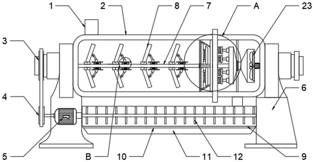
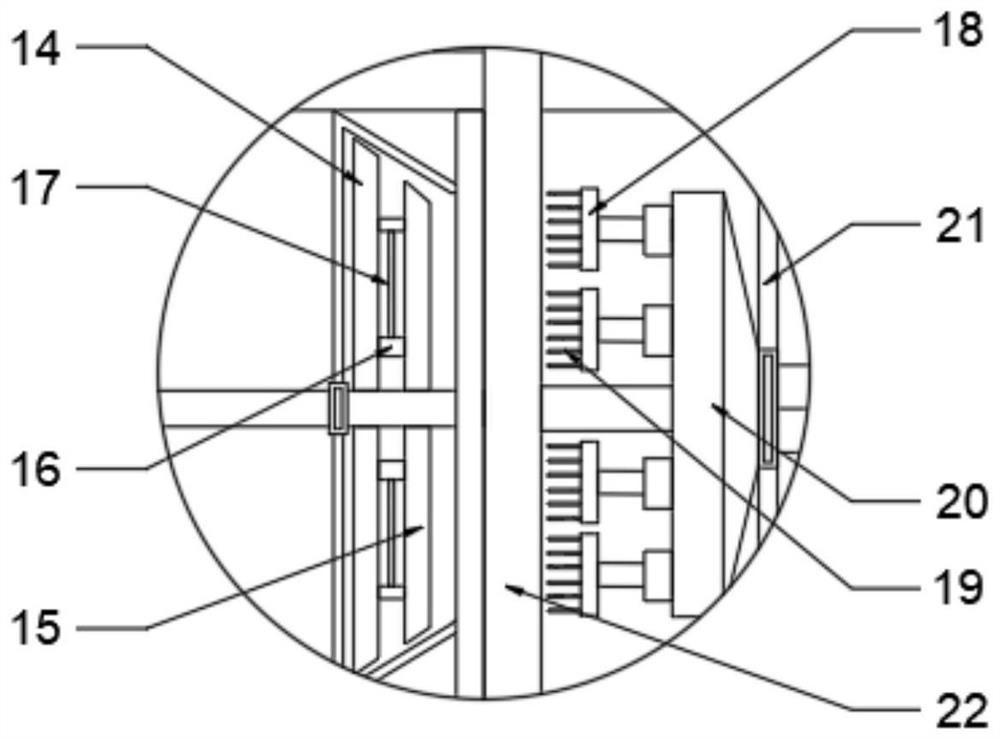
[0023] see Figure 1~4 , in the embodiment of the present invention, a stirring ball mill includes a stirring sleeve 2; the stirring sleeve 2 is fixedly installed on the installation platform 6; the installation platform 6 is provided with two; the inside of the stirring sleeve 2 A primary crushing mechanism is provided; the inside of the stirring sleeve 2 is provided with a dust removal mechanism corresponding to the primary crushing mechanism; the top of the stirring sleeve 2 is provided with a feed port 1; the bottom of the stirring sleeve 2 is connected to two The secondary crushing box 9; the inside of the secondary crushing box 9 is provided with a secondary pulverizer; the corresponding primary pulverizing mechanism and the secondary pulverizer 12 are provided with a drive mechanism on the mounting table 6; the bottom of the secondary pulverizing box 9 A discharge box 11 is provided.

[0024] Further, the drive mechanism includes a servo drive motor 5; the servo drive ...

Embodiment 2

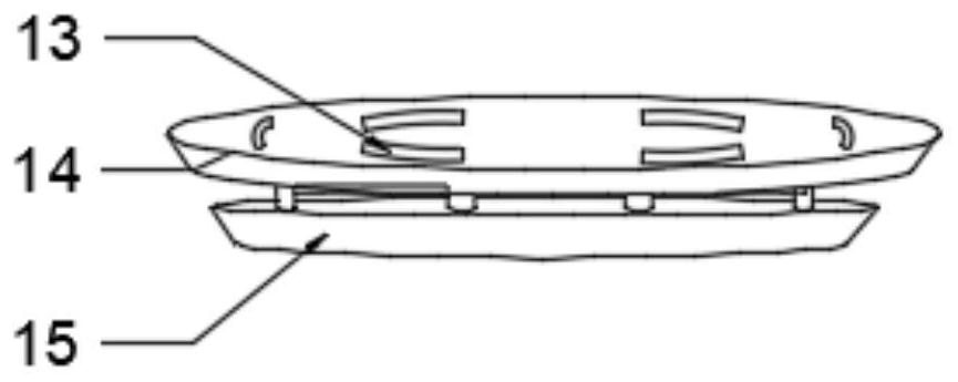
[0030] see Figure 5 , the secondary pulverizer 12 includes a connecting rotating shaft; a plurality of secondary distributing discs are evenly spaced on the connecting rotating shaft; several elliptical through holes are evenly arranged on the secondary powder disc; There are at least ten through holes evenly; the distance between the top of the distribution tray and the inner top of the No. 1 sieve plate 10 is less than the distance of the short axis of the ellipse through hole; The distance of the inner bottom is less than the distance of the minor axis of the ellipse through hole; the inner wall of the No. 1 sieve plate 10 is provided with irregular protrusions; through the setting of the secondary pulverizer 12, the ellipse through hole and the distribution tray, the The material is further pulverized; through the setting of the distance between the distribution tray and the inner wall of the No. 1 sieve plate 10, the material can also vibrate the No. 1 sieve plate 10 whe...


PUM


Abstract

The invention discloses a stirring type ball mill. The stirring type ball mill comprises a stirring sleeve; the stirring sleeve is fixedly mounted on mounting tables; the number of the mounting tablesis two; a primary crushing mechanism is arranged in the stirring sleeve; a dust removal mechanism corresponding to the primary crushing mechanism is arranged in the stirring sleeve; a feeding openingis formed in the top of the stirring sleeve; the bottom of the stirring sleeve communicates with a secondary crushing box through a discharging opening; a secondary crusher is arranged in the secondary crushing box; a driving mechanism corresponding to the primary crushing mechanism and the secondary crusher is arranged on the corresponding mounting table; and a discharging box is arranged belowthe secondary crushing box. The stirring type ball mill is good in crushing and grinding effect, sieve holes in a sieve plate can be effectively cleaned, and the sieve plate is prevented from being blocked to reduce the grinding and crushing efficiency.

Description

technical field [0001] The invention relates to the technical field of ball mills, in particular to a stirring ball mill. Background technique [0002] Agitator ball mills usually consist of horizontally or vertically arranged, approximately cylindrical grinding vessels. The agitator ensures vigorous movement of the grinding media by suitable stirring elements; the agitated ball mill is filled through an opening in or adjacent to an end wall. The grinding material suspension is continuously pumped through the grinding chamber. Suspended solids are ground or dispersed by impact and shear forces between the grinding media; the output depends on the structure and is achieved, for example, by cutouts in the grinding chamber wall at the end of the mill, where the grinding media are stopped by suitable separation devices ; For example, the separation device is formed by a separating screen, wherein the rotor or the rotor cover is arranged to rotate around the separating screen; ...

Claims


Application Information

Patent Timeline
Patent Type & Authority Applications(China)
IPC IPC(8): B02C17/16B02C17/18B02C23/16B07B1/52B07B1/55B07B1/50
CPCB02C17/16B02C17/163B02C17/18B02C23/16B07B1/50B07B1/524B07B1/55
Inventor 李浒李伯如李伯胜李长
Owner ZHUZHOU LIANXIN METAL CO LTD
Why Eureka
Try Eureka