Multi-process, multi-workpiece and double-station fixture for rudder shaft

A multi-workpiece, double-station technology, applied in the direction of manufacturing tools, metal processing machinery parts, clamping, etc., can solve the problems of strict dimensional tolerance requirements, high surface roughness requirements, and difficult processing, so as to reduce equipment usage costs , Reduce labor intensity and improve production efficiency

Active Publication Date: 2021-01-12
HARBIN JIANCHENG GRP
View PDF8 Cites 0 Cited by
  • Summary
  • Abstract
  • Description
  • Claims
  • Application Information

AI Technical Summary

Problems solved by technology

[0003] The purpose of the present invention is to solve the problem that the existing rudder shaft workpieces have strict dimensional tolerance requirements, high surface roughness requirements, high processing difficulty, easy to produce unqualified products, frequent repairs, and long processing time.

Method used


Image

  • Multi-process, multi-workpiece and double-station fixture for rudder shaft
  • Multi-process, multi-workpiece and double-station fixture for rudder shaft
  • Multi-process, multi-workpiece and double-station fixture for rudder shaft

Examples


specific Embodiment approach 1

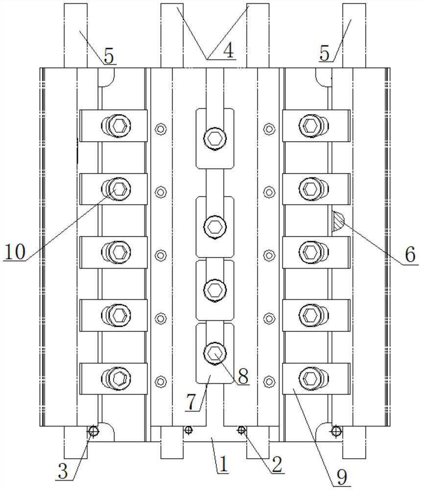
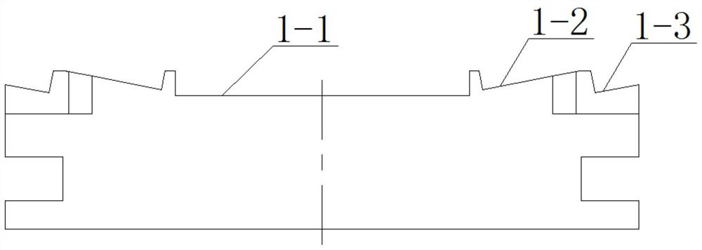
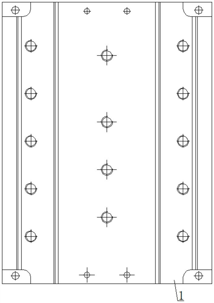
[0022] Specific implementation mode one: combine Figure 1-Figure 7 Describe this embodiment mode, a kind of rudder shaft multi-process, multi-workpiece, double station clamp described in this embodiment mode, it comprises clamp body 1, two first positioning pin shafts 2, two second positioning pin shafts 3, two An inner groove plug block 6, a plurality of U-shaped pressing plates 7, a plurality of first pressing plate connectors 8, a plurality of step pressing plates 9 and a plurality of second pressing plate connecting parts 10; the clip body 1 is a rectangular block, and the top of the rectangular block The surface is processed with a through groove 1-1 along the length direction of the rectangular block, and the side walls on both sides of the through groove 1-1 are sequentially processed with a first stepped slope 1-2 and a second stepped slope 1-3, and the through groove 1-1 The two ends of the groove bottom are respectively symmetrically machined with two first pin shaf...

specific Embodiment approach 2

[0023] Specific implementation mode two: combination figure 1 To illustrate this embodiment, the first pressure plate connecting piece 8 is a hexagon socket head bolt, the second pressure plate connection piece 10 is a hexagon socket head bolt, and the others are the same as in the first embodiment.

specific Embodiment approach 3

[0024] Specific implementation mode three: combination figure 1 To illustrate this embodiment, the U-shaped pressing plate 7 is a rectangular plate, and a U-shaped groove is processed on the rectangular plate, and the others are the same as in the first embodiment.


PUM


Abstract

The invention discloses a multi-process, multi-workpiece and double-station fixture for a rudder shaft, relates to a fixture, and aims to solve the problems that an existing rudder shaft workpiece isstrict in dimensional tolerance requirement, high in surface roughness requirement and high in machining difficulty, and is prone to generate unqualified products, products often need to be repaired,and the machining time is long. At present, no fixture for simultaneously performing multiple procedures of workpieces on three-axis equipment exists. The fixture comprises a fixture body, a first locating hinge pin, a second locating hinge pin, an inner groove plug block, a U-shaped pressing plate, a first pressing plate connecting piece, a step pressing plate and a second pressing plate connecting piece. A first stepped slope and a second stepped slope are sequentially machined on the two side walls of a through groove, and two first hinge pin locating holes are symmetrically machined in thetwo ends of the bottom of the through groove separately; and each rudder shaft slope workpiece to be machined is arranged on the surface of the second stepped slope in the length direction of the fixture body. and a plurality of stepped pressing plates are arranged on each rudder shaft slope workpiece to be machined. The fixture is applied to the field of multi-workpiece machining.

Description

technical field [0001] The invention relates to a fixture, in particular to a rudder shaft multi-process, multi-workpiece, double-station fixture used for multi-workpiece processing. Background technique [0002] At present, the rudder shaft workpiece in the prior art has strict dimensional tolerance requirements, takes a long time for equipment, and requires high surface roughness, which requires repeated turning over of the workpiece. The workpiece has many processes, multiple equipment is used to repeatedly turn over the surface, the surface roughness is high, and the processing is difficult. Using general-purpose flat-nose pliers for clamping, the clamping force is small, the size changes greatly, and unqualified products are prone to occur. The workpiece needs to be processed by three-axis equipment in the process of milling facets, and the process of milling inclined planes needs to be processed by four-axis equipment with flat-nose pliers on both sides. The dimensiona...

Claims


Application Information

Patent Timeline
IPC IPC(8): B23Q3/06
CPCB23Q3/061B23Q3/062
Inventor 王磊姚飞高伟马明礼王智莉
Owner HARBIN JIANCHENG GRP
Why Eureka
Try Eureka