
Metal film optical detection device and detection method

A detection device and optical detection technology, which is applied in the direction of measuring devices, optical testing of flaws/defects, and material analysis through optical means, which can solve the problem of workpieces being easily contaminated, reducing the accuracy of optical detection of metal films on workpieces, and increasing detection risks, etc. problem, to achieve the effect of increasing practicability, reducing the probability of pollution, and facilitating central positioning

Active Publication Date: 2021-10-22
NANTONG JIANGSEN ELECTRONICS TECH
View PDF3 Cites 0 Cited by
  • Summary
  • Abstract
  • Description
  • Claims
  • Application Information

AI Technical Summary

Problems solved by technology

[0003] In the prior art, when the metal film optical detection device detects the metal film, it usually needs to place the corresponding detection workpieces in the detection tank in sequence, so that the workpieces to be detected are easily contaminated during the detection and feeding process, increasing the detection capacity. risk, reducing the accuracy of optical detection of the metal film of the workpiece, so a metal film optical detection device and detection method are needed

Method used


Image

  • Metal film optical detection device and detection method
  • Metal film optical detection device and detection method
  • Metal film optical detection device and detection method

Examples


Embodiment Construction

[0026] The following will clearly and completely describe the technical solutions in the embodiments of the present invention with reference to the accompanying drawings in the embodiments of the present invention. Obviously, the described embodiments are only some, not all, embodiments of the present invention. Based on the embodiments of the present invention, all other embodiments obtained by persons of ordinary skill in the art without making creative efforts belong to the protection scope of the present invention.

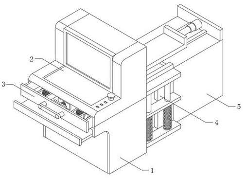
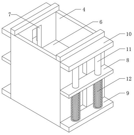
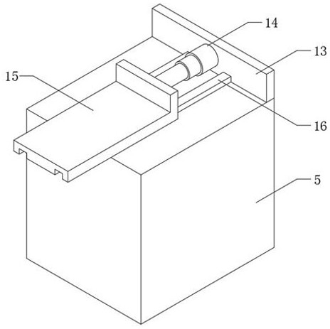
[0027] The present invention provides such Figure 1-5 The shown metal film optical detection device and detection method include a detection device body 1, one side of the detection device body 1 is interspersed with a detection drawer 3, and the other side of the detection device body 1 is fixedly provided with a feeding box 4, One side of the feeding box 4 is fixedly provided with a positioning platform 5, the top of one side of the detection device body 1 ...


PUM


Abstract

The invention discloses a metal film optical detection device and detection method. The metal film optical detection device comprises a detection device body, a detection drawer is arranged on one side of the detection device body in a penetrating mode, a feeding box is fixedly arranged on the other side of the detection device body, and a positioning table is fixedly arranged on one side of the feeding box; a positioning plate is arranged at one end of the inner wall of the feeding box in a penetrating mode, through grooves are formed in the middle positions of the two sides of the feeding box correspondingly, sliding blocks are arranged in the two through grooves in a sliding mode correspondingly, and the two sliding blocks are fixedly arranged in the middle positions of the two sides of the positioning plate correspondingly. According to the invention, a to-be-detected workpiece containing a metal film is placed on the inner wall of the feeding box, a push plate pushes the workpiece containing the metal film at the top end of the feeding box to move, the workpiece stably moves into the detection drawer, the probability that the device to be detected is polluted is reduced, the detection efficiency of the optical detection equipment is improved, and the practicability of the optical detection device for the metal film is improved.

Description

technical field [0001] The invention relates to the field of metal film optical detection devices, in particular to a metal film optical detection device and a detection method. Background technique [0002] The optical inspection device is based on the optical principle to detect common defects encountered in welding production. The optical inspection device has a comprehensive verification function, which can reduce false positives of inspection and ensure that the inspection program is flawless. It can check defective samples in storage, and all known defects must be checked while minimizing the number of false positives allowed. Before making any program adjustments to reduce false positives, check to see if previously detected defects have been corroborated by the repair station. Quality assurance of inspection programs through comprehensive verification for dedicated manufacturing and verification while tracking false positives. [0003] In the prior art, when the me...

Claims


Application Information

Patent Timeline
Patent Type & Authority Applications(China)
IPC IPC(8): G01N21/88G01N21/01B25H1/12
CPCG01N21/88G01N21/01B25H1/12
Inventor 陈宇王晓兵陈峰
Owner NANTONG JIANGSEN ELECTRONICS TECH
Learn More