Eureka AIR delivers breakthrough ideas for toughest innovation challenges, trusted by R&D personnel around the world.

Electric monorail crane locomotive

A technology for monorail cranes and locomotives, applied to motor vehicles, brakes where brake components interact with rails, and railway vehicles, etc., can solve problems such as engine exhaust pollution, impact on locomotive mileage, noise pollution, etc., and improve working conditions , Occupy small space, work reliably

Pending Publication Date: 2021-01-12
SHANDONG ENERGY HEAVY EQUIP MFG GRP TAIZHUANG ENG EQUIP MFG CO LTD
View PDF0 Cites 3 Cited by
  • Summary
  • Abstract
  • Description
  • Claims
  • Application Information

AI Technical Summary

Problems solved by technology

Traditional monorail locomotives are powered by explosion-proof diesel engines and hydraulically driven. The existing problems are engine exhaust pollution and serious noise pollution, which are unsolvable problems in the working conditions of coal mine roadways.
At the same time, in order for the electric monorail locomotive to operate normally, in addition to solving a series of technologies such as the power drive device, transmission system, and hydraulic control system, the motor frequency conversion control device and battery device must be carried with the vehicle. The dimensions and length of these devices are relatively long , when passing through track curves and ramps, it is easy to be stuck; at the same time, the electric capacity of the battery directly affects the cruising range of the locomotive. At present, my country's coal mining industry is not allowed to charge underground in coal mines for safety reasons, and replacement batteries can be used To improve the cruising range of the locomotive, it is necessary to develop the quick replacement function of the battery cabinet

Method used


Image

  • Electric monorail crane locomotive
  • Electric monorail crane locomotive
  • Electric monorail crane locomotive

Examples


Embodiment Construction

[0048] In order to make those skilled in the art better understand the technical solution of the present invention, the technical solution of the present invention is clearly and completely described below in conjunction with the accompanying drawings of the present invention. Based on the embodiments in this application, those of ordinary skill in the art will Other similar embodiments obtained without creative work shall all fall within the scope of protection of this application.

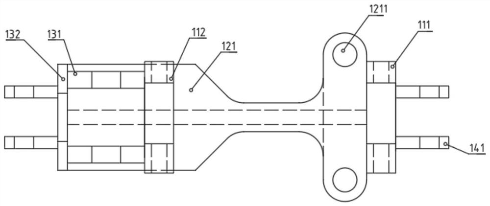
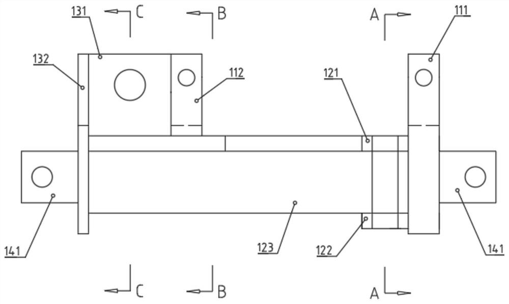
[0049] Such as figure 1 As shown, the electric monorail locomotive provided in this specific embodiment includes a driver's cab, a passenger compartment cabinet, a battery cabinet for installing a battery pack, a frequency conversion cabinet for installing a motor frequency conversion control device, and a driver's cab for hanging the cab. Hanging device, hanging device for passenger compartment cabinet, load hanging device for hanging cargo, two mutually hinged cabinet hanging devices and multip...


PUM


Abstract

The invention discloses an electric monorail crane locomotive which comprises a battery cabinet used for installing a storage battery pack, a frequency conversion cabinet used for installing a motor frequency conversion control device, two cabinet body hanging devices hinged to each other and a plurality of driving devices hinged in sequence. Each cabinet body hanging device comprises a cabinet body hanging support used for hanging a cabinet body and a plurality of hanging mechanisms which are hung on an I-shaped rail of the monorail crane and can walk on the I-shaped rail, and the hanging mechanisms are connected to the cabinet body hanging support in a horizontal rotating mode. The battery cabinet and the frequency conversion cabinet are detachably hung on cabinet body hanging supports of the two cabinet body hanging devices respectively, the driving device is driven by a motor, and one hanging mechanism is hinged to the driving device adjacent to the hanging mechanism. The electricmonorail crane locomotive provided by the invention is powered by the storage battery to realize electric driving, the green operation of zero emission, no pollution, low noise and the like of the monorail crane locomotive are realized, and the underground working environment of a coal mine is improved.

Description

technical field [0001] The invention belongs to the technical field of coal mine auxiliary transportation equipment, in particular to an electric monorail locomotive. Background technique [0002] The coal industry is the pillar industry of our country, and the development of energy-saving, environmentally friendly, efficient and fast auxiliary transportation methods is an important task for the construction of my country's coal mine industry. The monorail crane system is an important auxiliary transportation system in coal mines. The monorail crane locomotive is a modern air transportation equipment in the coal mine. The I-shaped steel monorail, that is, the I-shaped track, is hung on the top of the roadway with a ring chain, and the locomotive travels back and forth on the monorail. Transportation has the advantages of convenience, speed, and large transportation volume. Traditional monorail locomotives are powered by explosion-proof diesel engines and driven by hydraulic...

Claims


Application Information

Patent Timeline
Patent Type & Authority Applications(China)
IPC IPC(8): B61B12/02B61H7/12
CPCB61B12/02B61B12/028B61H7/12
Inventor 张洪建冯军马林赵令印郑俊成曲业伟周利魏凤颜玉刘秀荣白树文
Owner SHANDONG ENERGY HEAVY EQUIP MFG GRP TAIZHUANG ENG EQUIP MFG CO LTD
Why Eureka
Eureka Blog
Learn More