

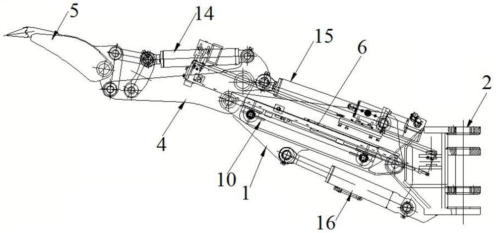
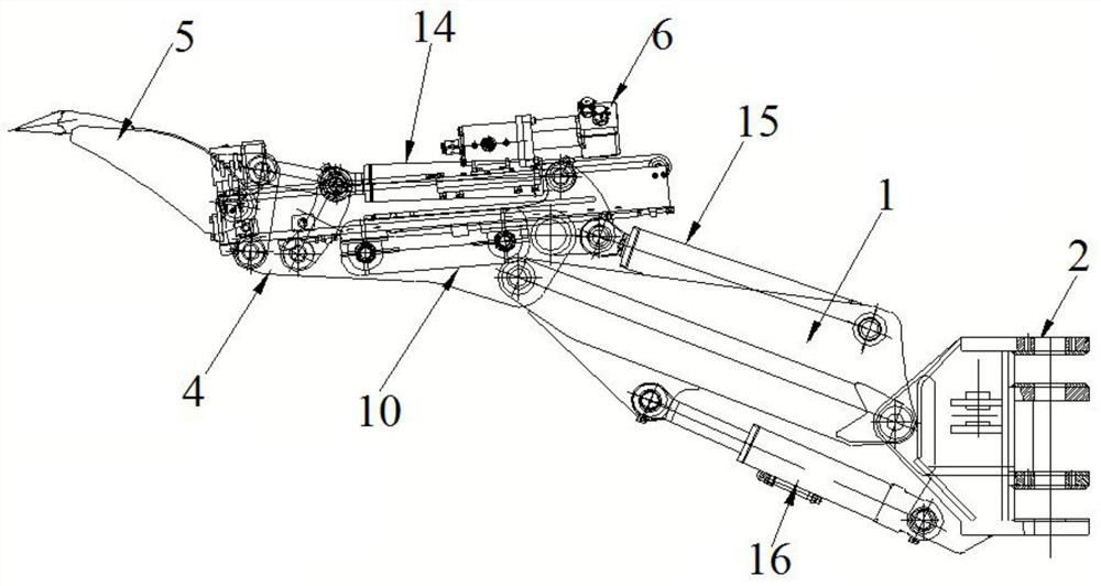
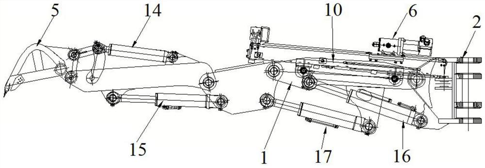
Digging and exploring arm support mechanism
A technology of boom and boom, which is applied in the field of boom mechanism for excavation, which can solve the problems of large volume of exploration drilling rig, long idle time, stuck drill and brazing, etc., so as to reduce the types of equipment and operators, and improve the efficiency of roadway excavation , Avoid the effect of jamming drill
- Summary
- Abstract
- Description
- Claims
- Application Information
AI Technical Summary
Problems solved by technology
Method used
Image

Examples
Embodiment Construction
[0029] The following will clearly and completely describe the technical solutions in the embodiments of the present invention with reference to the accompanying drawings in the embodiments of the present invention. Obviously, the described embodiments are only some of the embodiments of the present invention, not all of them. Based on the embodiments of the present invention, all other embodiments obtained by persons of ordinary skill in the art without making creative efforts belong to the protection scope of the present invention.
[0030] The purpose of the present invention is to provide a digging boom mechanism to solve the problems existing in the prior art, make the digging boom modular, facilitate the transformation of existing equipment, and at the same time meet the needs of digging and detection during roadway excavation .
[0031] In order to make the above objects, features and advantages of the present invention more comprehensible, the present invention will be ...
PUM
 Abstract
Description
Claims
Application Information