Combustion chamber and gas engine

A gas engine and combustion chamber technology, which is applied to combustion engines, internal combustion piston engines, gaseous engine fuels, etc., can solve the problems of inability to achieve a roof type combustion chamber, low thermal efficiency of gas engines, and inability to further improve tumble flow intensity, etc. Reduced risk of knocking, improved reliability, increased effect of turbulent kinetic energy

Active Publication Date: 2021-01-12
WEICHAI POWER CO LTD
View PDF7 Cites 5 Cited by
  • Summary
  • Abstract
  • Description
  • Claims
  • Application Information

AI Technical Summary

Problems solved by technology

In order to improve the combustion characteristics of the gas engine, the existing technology generates a corresponding weak tumble flow by modifying the intake port structure of the cylinder head. However, because it still uses the combustion chamber structure of the diesel engine, the valve stem cannot be tilted, so it cannot achieve a gas engine similar to that of a gasoline engine. The canopy-shaped combustion chamber, and the piston matched with the weak tumble flow channel is still a traditional straight-mouthed piston. Therefore, the tumble flow intensity cannot be further improved in the prior art, which ultimately leads to a low thermal efficiency of the gas engine

Method used


Image

  • Combustion chamber and gas engine
  • Combustion chamber and gas engine
  • Combustion chamber and gas engine

Examples


Embodiment Construction

[0052]The technical solutions in the embodiments of the present invention will be clearly and completely described below in conjunction with the accompanying drawings in the embodiments of the present invention. Obviously, the described embodiments are only a part of the embodiments of the present invention, rather than all the embodiments. Based on the embodiments of the present invention, all other embodiments obtained by those of ordinary skill in the art without creative work shall fall within the protection scope of the present invention.

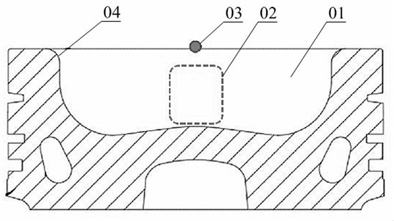
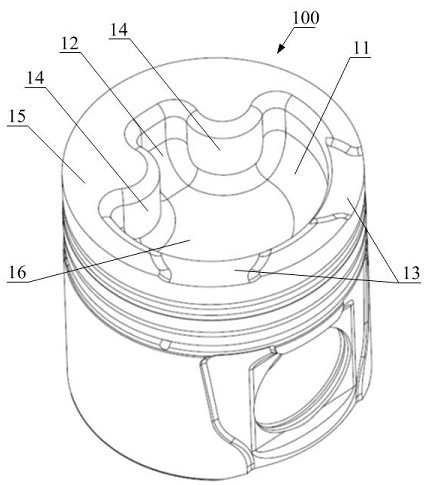
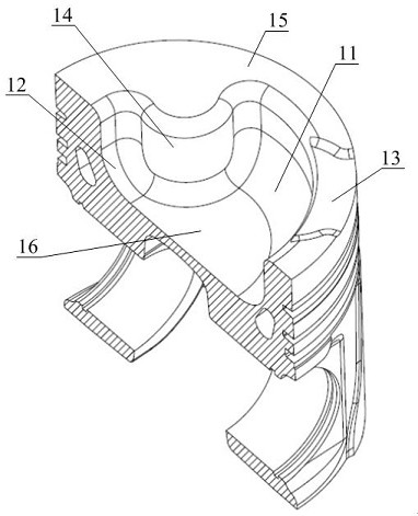
[0053]Please refer toFigure 2 to Figure 10 ,figure 2 It is an oblique view of the overall structure of the piston in a specific embodiment of the invention;image 3 forfigure 2 A longitudinal sectional view of the middle piston;Figure 4 It is a top view of the piston in a specific embodiment of the present invention;Figure 5 It is a characteristic diagram of the cross section of the pit in the specific embodiment of the present invention;Figure ...


PUM


Abstract

The invention discloses a combustion chamber which is applied to a gas engine. The combustion chamber comprises a piston upper top face located at the top of a piston and a combustion chamber pit sunken downwards relative to the piston upper top face, wherein two flow guide protruding parts protruding towards the inner side of the combustion chamber pit are arranged on the circumferential side wall in the combustion chamber pit, the two flow guide protruding parts are located below two air inlet valves correspondingly, the upper end faces of the flow guide protruding parts are connected with the piston upper top face, and the lower ends of the flow guide protruding parts are connected with the bottom face of the combustion chamber pit. The combustion chamber pit comprises a first flow guide pit located below the exhaust valve and a second flow guide pit located between the two flow guide protruding parts. The first flow guide pit is communicated with the second flow guide pit, and theside surface of the flow guide protruding part forms a smooth transition face between the first flow guide pit and the second flow guide pit. According to the combustion chamber, the tumble intensitycan be enhanced in the compression process, and tumble is violently broken into turbulent flow in the final stage of compression; and therefore the flame spreading speed is increased, and turbulent kinetic energy and heat efficiency are improved. The invention further discloses a gas engine.

Description

Technical field[0001]The invention relates to the technical field of engines, in particular to a combustion chamber and a gas engine.Background technique[0002]At present, gas engines are generally modified on the basis of diesel engines. For diesel engines, the vortex generated by the swirling air passage helps to a certain extent the mixing of oil and air, thereby achieving the goal of high efficiency combustion and low pollutant emissions. Gas engines are mostly premixed combustion, which does not require high vortex intensity. The fuel has been mixed with air during the intake process, and after the spark plug ignites to generate a fire core, the ideal state is that there is high turbulent kinetic energy in the cylinder during the combustion process. The increase of turbulent kinetic energy will speed up the flame propagation speed, which is of great significance for improving the combustion process of the gas engine and reducing the cycle variation. If the large-scale flow such ...

Claims


Application Information

Patent Timeline
Patent Type & Authority Applications(China)
IPC IPC(8): F02B23/10F02F3/26F02B43/04F02B43/06
CPCF02B23/10F02B43/04F02B43/06F02B2023/106F02B2023/108F02F3/26Y02T10/12Y02T10/30
Inventor 李卫吕顺王慧潘洁
Owner WEICHAI POWER CO LTD
Why Eureka
Try Eureka