Combustion device and method for a dual-fuel engine based on a dual-needle valve injector

A dual-fuel engine and combustion device technology, which is applied to combustion engines, machines/engines, fuel injection devices, etc., can solve the problem that the stability and fuel economy of the engine need to be improved, the stability of the engine is affected, and the output power of the engine is reduced. problem, to achieve the effect of being conducive to flame propagation, fast and flexible switching, and improving the burning rate

Active Publication Date: 2020-11-20
HARBIN ENG UNIV
View PDF2 Cites 0 Cited by
  • Summary
  • Abstract
  • Description
  • Claims
  • Application Information

AI Technical Summary

Problems solved by technology

There are three problems: one is that two installation holes need to be arranged on the cylinder head, and the area of ​​the cylinder head is certain, which increases the loss of the cylinder head; the other is that when the gas mode fails or starts and idles, it needs to switch to diesel mode, due to the different supply methods of diesel and natural gas, when the two modes are switched, it will cause engine fluctuations, and the two injectors will also be switched at the same time, which will cause a switching delay and affect the stability of the engine; in addition, diesel / Natural gas dual-fuel engine gas supply method generally adopts intake port injection, which makes the charging efficiency low and reduces the output power of the engine
However, the structure of the device is relatively complicated, and the working stability and fuel economy of the engine still need to be improved.

Method used


Image

  • Combustion device and method for a dual-fuel engine based on a dual-needle valve injector
  • Combustion device and method for a dual-fuel engine based on a dual-needle valve injector
  • Combustion device and method for a dual-fuel engine based on a dual-needle valve injector

Examples


Embodiment Construction

[0034] In order to make the above-mentioned purposes, features and advantages of the present invention more obvious and understandable, the present invention will be further described below in conjunction with the accompanying drawings:

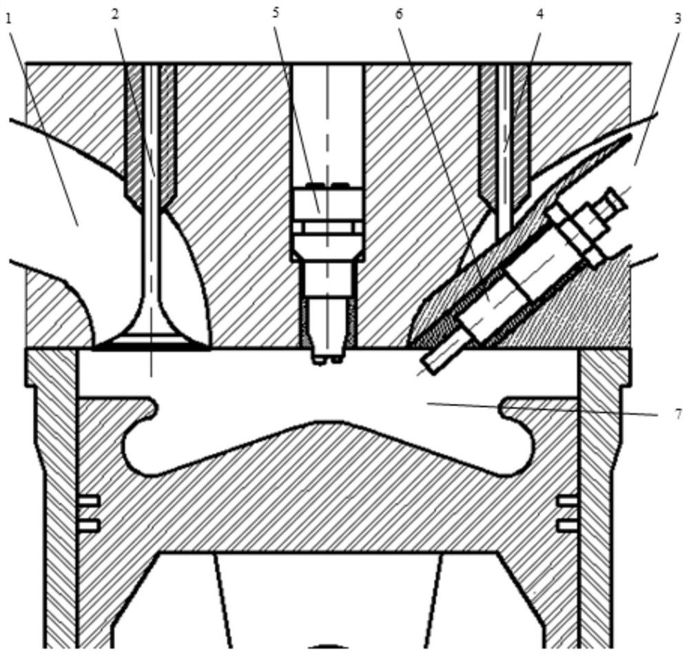
[0035] figure 1 It is a structural schematic diagram of a dual-fuel engine combustion device based on a dual-needle valve injector;

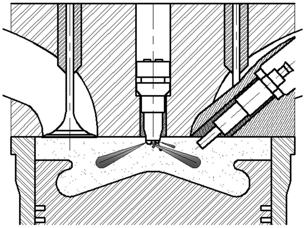
[0036] figure 2 It is a schematic diagram of the working state of the double-needle valve injector before the piston compression top dead center in the gas mode of the present invention and a distribution diagram of the concentration of the combustible mixture in the cylinder;

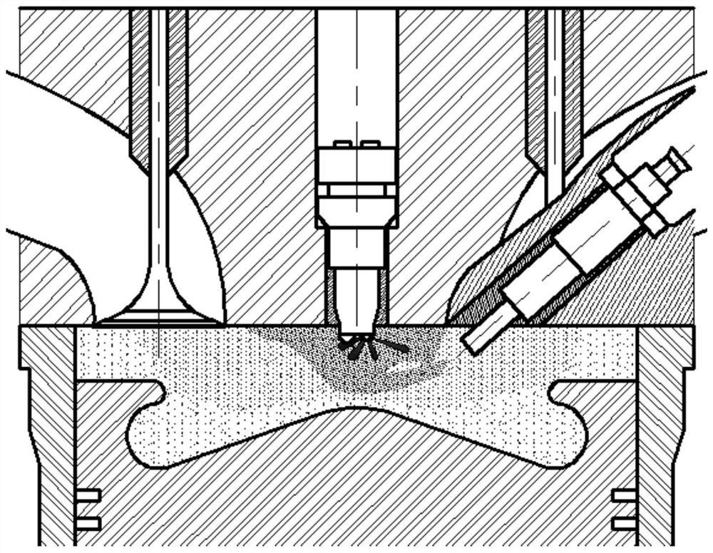
[0037] image 3 It is a schematic diagram of the working state of the double-needle valve injector before the piston compression top dead center in the diesel mode of the present invention;

[0038] Figure 4 It is a schematic diagram of the nozzle part of the double-needle valve fuel injector of the present invention;

[0039] In...


PUM


Abstract

The invention relates to the field of dual-fuel engines, in particular to a dual-fuel engine combustion device and method based on a double-needle-valve oil atomizer. The dual-fuel engine combustion device based on the double-needle-valve oil atomizer comprises an air distribution system, a fuel supply system and a combustion chamber system. The air distribution system is located on an air cylinder cover. An air inlet part and an exhaust part are symmetrically distributed at the two ends of the air cylinder cover. The fuel supply system is located on the air cylinder cover and is right opposite to the lower combustion chamber system. The combustion chamber system is formed by connecting the air cylinder cover and an air cylinder through bolts. The dual-fuel engine combustion method based on the double-needle-valve oil atomizer comprises the steps that firstly, the dual-fuel engine is in a gas mode; and secondly, the diesel oil mode is switched when the dual-fuel engine is in starting and idling work conditions. Dual-fuel engine gas and fuel oil dual modes are rapidly and flexibly switched, mixed gas concentration layering in the dual-fuel engine gas mode is achieved, and accordingly power performance, economic efficiency and discharging performance of the fuel are improved.

Description

technical field [0001] The invention relates to the field of dual-fuel engines, in particular to a dual-fuel engine combustion device and method based on a double-needle valve injector. Background technique [0002] Due to the development of internal combustion engines, problems such as energy crisis and air pollution have been brought about. In urban environmental pollution, CO, HC compounds, and NO emitted from vehicle exhaust X , and PM have become the main pollution sources of urban atmospheric environment. This causes severe weather phenomena such as urban smog and acid rain. SO in ship engine exhaust X and NO X It has become the main source of pollution in ports, straits, sea areas with heavy ship traffic and inland river surrounding areas. The pollution caused by internal combustion engine emissions to the atmospheric environment has attracted widespread attention from the international community. Countries around the world have successively formulated strict emis...

Claims


Application Information

Patent Timeline
Patent Type & Authority Patents(China)
IPC IPC(8): F02D19/06F02D19/08F02M21/02F02M61/10F02M61/14F02B31/04
CPCF02B31/04F02D19/0615F02D19/08F02M21/0263F02M61/10F02M61/145Y02T10/12Y02T10/30
Inventor 杨立平罗岩宋恩哲姚崇范立云
Owner HARBIN ENG UNIV
Why Eureka
Try Eureka