A combustion chamber and a gas engine

A gas engine and combustion chamber technology, which is applied to combustion engines, internal combustion piston engines, engine components, etc., can solve the problems of unfavorable gas fuel premixed combustion, poor swirl ratio consistency, and low tumble flow intensity, so as to improve gas combustion characteristics , Accelerate the propagation speed, improve the effect of thermal efficiency

Active Publication Date: 2020-12-22
WEICHAI POWER CO LTD
View PDF6 Cites 0 Cited by
  • Summary
  • Abstract
  • Description
  • Claims
  • Application Information

AI Technical Summary

Problems solved by technology

Thanks to the squeeze movement at the end of compression, the flame spreads faster laterally, but the flame spreads slowly in the combustion chamber 01, which is not conducive to the premixed combustion of gaseous fuels, such as figure 1 As shown, the rectangular dotted frame area near the spark plug 03 is the flame propagation low speed zone 02. The horizontal direction mentioned in this article refers to the radial direction of the cylinder, and the longitudinal direction refers to the axial direction of the cylinder.
In addition, the area 04 along the top of the piston is poorly cooled, which is an area with a high risk of knocking
In the high-speed and high-load area, the squish flow may blow out the fire core and adversely affect the ignition stability
[0004] In addition, for a gas engine transformed from a diesel engine, the intermediate air intake method and casting deviation will lead to poor consistency of swirl ratio, which in turn will lead to poor air intake consistency of each cylinder
On the premise that the valve stem cannot be tilted, although the intake port can be improved to produce a large-scale weak tumble motion in the cylinder, however, because the canopy-shaped combustion chamber similar to a gasoline engine cannot be achieved, the cylinder The tumble flow intensity is low, which is not conducive to the premixed combustion of gas fuel

Method used


Image

  • A combustion chamber and a gas engine
  • A combustion chamber and a gas engine
  • A combustion chamber and a gas engine

Examples


Embodiment Construction

[0039] The following will clearly and completely describe the technical solutions in the embodiments of the present invention with reference to the accompanying drawings in the embodiments of the present invention. Obviously, the described embodiments are only some, not all, embodiments of the present invention. Based on the embodiments of the present invention, all other embodiments obtained by persons of ordinary skill in the art without making creative efforts belong to the protection scope of the present invention.

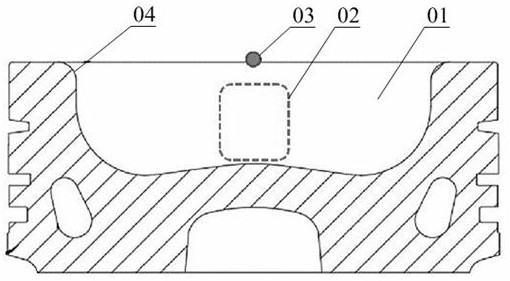
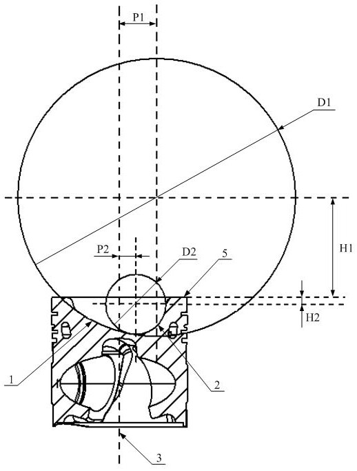
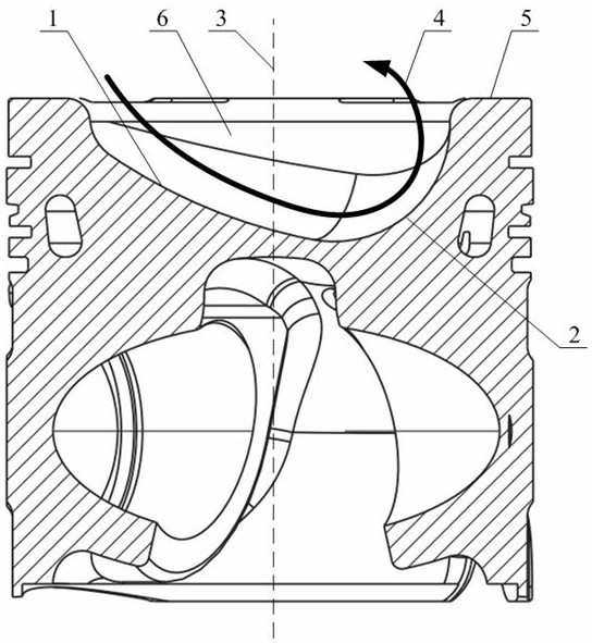
[0040] Please refer to Figure 2 to Figure 5 , figure 2 It is a schematic longitudinal sectional view of the combustion chamber in a specific embodiment of the present invention; image 3 It is a schematic diagram of tumble flow in a specific embodiment of the present invention; Figure 4 It is another longitudinal cross-sectional schematic view of the combustion chamber in a specific embodiment of the present invention; Figure 5 It is a schematic diagram o...


PUM


Abstract

The invention discloses a combustion chamber and a gas engine. The combustion chamber comprises a combustion chamber pit which is located in the top of a piston and concaves downwards relative to theupper top face of the piston, the combustion chamber pit comprises an airflow guiding pit and an airflow casting pit which are sequentially arranged, the bottom face of the airflow guiding pit is a tumble flow guide face, and the bottom face of the airflow casting pit is a tumble flow generation face; the tumble flow guide face gradually extends downwards from the upper edge of one side of the combustion chamber pit and is in smooth transition connection with the tumble flow generation face, and the tumble flow generation face is an inwards-concave curved face in smooth transition from the lower end of the tumble flow guide face to the upper edge of the other side of the combustion chamber pit. By means of the asymmetric combustion chamber pit structure, mixed gas rolls in the combustion chamber and forms tumble flow, so that turbulent energy of spark plug accessories is improved, transverse and longitudinal propagation speed of flames is increased, combustion characteristics of fuel gas are improved, and thermal efficiency of the gas engine is improved. The invention further discloses the gas engine comprising the combustion chamber.

Description

technical field [0001] The invention relates to the technical field of engines, in particular to a combustion chamber and a gas engine. Background technique [0002] At present, natural gas engines are generally modified on the basis of diesel engines. For a diesel engine, the vortex generated by the swirling air passage helps the oil jet to mix with the air to a certain extent, so as to achieve high-efficiency combustion and low pollutant emissions. The gas engine is mostly premixed combustion. The fuel has been mixed with the air during the intake process. After the spark plug is ignited to form a fire core, the ideal state is that there is a high turbulent kinetic energy in the cylinder during the combustion process. The increase of turbulent kinetic energy will accelerate the speed of flame propagation, which is of great significance for improving the combustion process of gas engines and reducing cycle fluctuations. If the large-scale flow of vortex continues to exist...

Claims


Application Information

Patent Timeline
Patent Type & Authority Patents(China)
IPC IPC(8): F02F3/26F02B23/08
CPCF02B23/08F02F3/26Y02T10/12
Inventor 李卫吕顺张海瑞潘洁
Owner WEICHAI POWER CO LTD
Why Eureka
Try Eureka