
Image rendering method and device, electronic equipment and storage medium

An image rendering and target image technology, applied in the field of image processing, can solve problems such as poor rendering effect, and achieve the effect of improving rendering effect

Pending Publication Date: 2021-01-12
GUANGZHOU HUYA TECH CO LTD
View PDF0 Cites 6 Cited by
  • Summary
  • Abstract
  • Description
  • Claims
  • Application Information

AI Technical Summary

Problems solved by technology

[0004] However, in the process of calculating the projection of virtual objects, some calculation strategies may have some faults in the process of calculating the projection, resulting in poor rendering effect

Method used


Image

  • Image rendering method and device, electronic equipment and storage medium
  • Image rendering method and device, electronic equipment and storage medium
  • Image rendering method and device, electronic equipment and storage medium

Examples


Embodiment approach

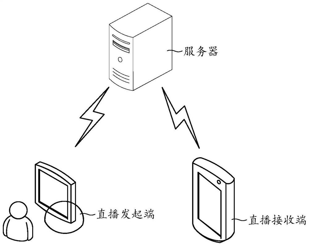
[0058] see Figure 5 , Figure 5 It shows a schematic flowchart of the image rendering method provided in this application. As a possible implementation, the image rendering method may include the following steps:

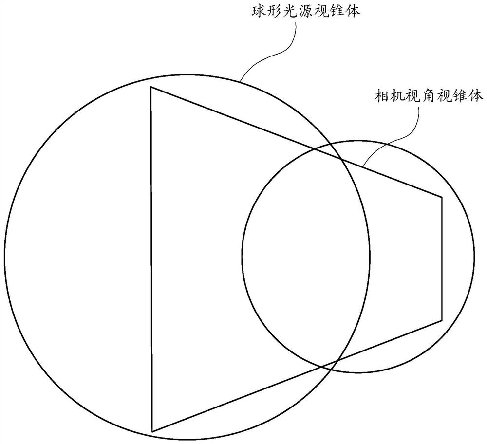
[0059] Step 201, for the virtual object of the target image, calculate the target projection matrix of the virtual object under the viewing frustum of the spherical light source.

[0060] Step 203: Generate a target shadow map corresponding to the virtual object according to the target projection matrix.

[0061] Step 205, rendering the target shadow map to the target image.

[0062] combine figure 2 as well as image 3 As shown, in some embodiments, when the electronic device executes the image rendering method provided by the present application, for the virtual object in the target image, the electronic device may not use the truncated frustum based on the camera perspective to generate shadows, but Based on a spherical light source viewing frustum, the ta...


PUM


Abstract

The invention provides an image rendering method and device, electronic equipment and a storage medium, and relates to the technical field of image processing. The method aims at a virtual object in atarget image to generate a target shadow map corresponding to the virtual object according to a target projection matrix by calculating the target projection matrix of the virtual object under a spherical light source view cone, and therefore the target shadow map is rendered to a target image; thus, in the projection generation process, the same shadow map can be located in the same view frustum, so that a fault is prevented from occurring between every two adjacent view frustums, and the rendering effect of the shadow map is improved.

Description

technical field [0001] The present application relates to the technical field of image processing, and in particular, to an image rendering method, device, electronic equipment, and storage medium. Background technique [0002] In scenarios such as webcasting, technologies such as AR (Augmented Reality, Augmented Reality) may be used to render some virtual objects in the live image to enrich the live content in the live image and improve the effect of the live broadcast. [0003] Among them, in order to improve the real effect of the virtual object, effects such as shadows of the virtual object can also be rendered in the live image, so as to simulate the object projection in the real scene. [0004] However, in the process of calculating the projection of the virtual object, some calculation strategies may have some faults in the process of calculating the projection, resulting in poor rendering effect. Contents of the invention [0005] The purpose of the present applic...

Claims


Application Information

Patent Timeline
Patent Type & Authority Applications(China)
IPC IPC(8): G06T15/04G06T15/60G06T15/00G06T19/00H04N21/2187H04N21/2343H04N21/4402
CPCG06T15/04G06T15/60G06T15/005G06T19/006H04N21/2187H04N21/2343H04N21/234309H04N21/4402H04N21/440218
Inventor 叶广荣
Owner GUANGZHOU HUYA TECH CO LTD
Learn More