A kind of cable recovery equipment

A technology for recycling equipment and cables, applied in the field of cable recycling equipment, can solve problems such as inability to brush down, inconvenient cleaning, and cables not being fixed, and achieve the effects of preventing large scratching force, facilitating cleaning, and preventing displacement

Active Publication Date: 2022-05-17
砀山红旗电缆有限公司
View PDF0 Cites 0 Cited by
  • Summary
  • Abstract
  • Description
  • Claims
  • Application Information

AI Technical Summary

Problems solved by technology

[0004] 1. The cable is not fixed. When cleaning, it will be displaced by the friction of the brush plate, which will affect the cleaning effect.
[0005] 2. Dust and other dirt adhering to the surface of the cable also contain relatively hard impurities, which have a higher adhesion strength to the cable. Only using the brush plate can not completely brush it off, which will affect the effect of washing.
[0006] 3. After the cable is cleaned for the first time, although the cleaned waste water can filter impurities through the filter screen, the filtered dust accumulates on the filter screen, and the filter screen is always in contact with the cleaning water source and is stirred by the blades. The dust is easy to dissolve in water, and then flows into the end of the treatment tank near the suction pipe, which reduces the cleanliness of the cleaning water source, thereby reducing the treatment efficiency of the cleaning wastewater. Cleaning efficiency, at the same time, after cleaning the dust on the filter, the brush is easy to get dirty and inconvenient to clean

Method used


Image

  • A kind of cable recovery equipment
  • A kind of cable recovery equipment
  • A kind of cable recovery equipment

Examples


Embodiment Construction

[0041] The technical solutions of the present invention will be further described below in conjunction with the accompanying drawings and through specific implementation methods.

[0042] Wherein, the accompanying drawings are only for illustrative purposes, showing only schematic diagrams, rather than physical drawings, and should not be construed as limitations on this patent; in order to better illustrate the embodiments of the present invention, some parts of the accompanying drawings will be omitted, Enlarged or reduced, does not represent actual product size.

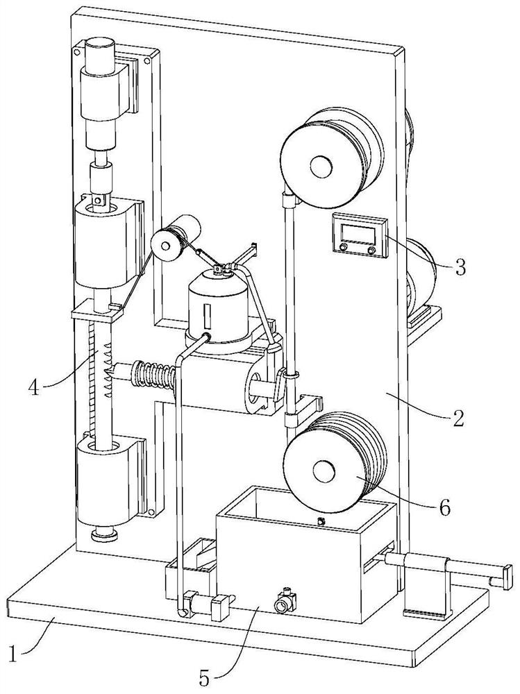
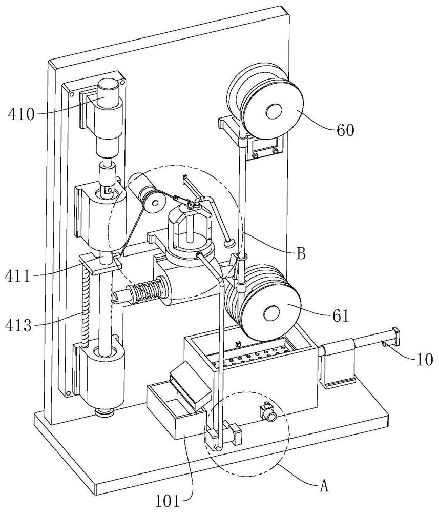
[0043] refer to Figure 1 to Figure 10 The shown cable recovery equipment includes a base 1 and a vertical plate 2, and the vertical plate 2 is fixed on the top of the base 1, and also includes a controller 3, a scraping mechanism 4, a flushing mechanism 5 and a conveying mechanism 6. The controller 3 is fixed on the outer wall of the vertical plate 2, and the scraping mechanism 4 is arranged on the outer wall of...


PUM


Abstract

The present invention relates to the field of cable cleaning devices, in particular to a cable recycling device, which includes a base and a vertical plate, and also includes a controller, a scraping mechanism, a flushing mechanism and a conveying mechanism. The scraping mechanism includes a scraping head, a push assembly and a side pressure assembly , the flushing mechanism includes a water supply tank, a conveying assembly and a spray washing assembly, the conveying mechanism includes a first set of rollers, a second set of rollers and a rotating assembly, the rotating assembly is arranged on the back of the stand, the first set of rollers and the second The sets of rollers are arranged symmetrically on the outer wall of the vertical plate, the first set of rollers is socketed with the rotating assembly, the second set of rollers is rotatably connected with the vertical plate, the pushing assembly, the conveying assembly and the rotating assembly are connected with the controller For electrical connection, the present invention and a cable recovery device can effectively fix the cable, prevent its displacement, scrape more thoroughly, and have higher efficiency. At the same time, impurities can be discharged in time to prevent pollution of the cleaning water source, and it is beneficial to cleaning Sewage recycling.

Description

technical field [0001] The invention relates to the field of cable cleaning devices, in particular to a cable recovery device. Background technique [0002] When the cables cannot be used normally, they will be classified as waste disposal. Some cables are returned to the factory for repair and replacement by the manufacturer, and others that cannot be replaced will generally be classified as scrap copper and disposed of by various departments. The waste materials recyclers in the area carry out the purchase and processing. The waste materials recyclers are responsible for stripping the cables and recycling the copper in them. The copper obtained from the cables is then sent to the copper factory to process cables or other copper products, or directly smelted into copper ingots. In order to save resources, the recycled cables with better performance must be reused, and the surface of the recycled cables is basically covered with dirt, dust and other dirt, so the recycled cab...

Claims


Application Information

Patent Timeline
Patent Type & Authority Patents(China)
IPC IPC(8): B08B1/00B08B1/02B08B3/02B08B3/14B08B13/00
CPCB08B1/005B08B1/008B08B1/02B08B3/022B08B3/14B08B13/00Y02W30/82
Inventor 姜瑞玉
Owner 砀山红旗电缆有限公司
Why Eureka
Try Eureka