Eureka AIR delivers breakthrough ideas for toughest innovation challenges, trusted by R&D personnel around the world.

Mechanical lower limb machining device

A technology for processing devices and lower limbs, applied in positioning devices, shearing devices, metal processing equipment, etc., can solve the problem of inability to achieve fast fixation, inability to process cutting materials in time, and inability to effectively perform fast and safe cutting, etc. problems, to achieve the effect of solving cutting, facilitating centralized processing and ensuring safety

Pending Publication Date: 2021-01-15
德清博发智能科技有限公司
View PDF8 Cites 1 Cited by
  • Summary
  • Abstract
  • Description
  • Claims
  • Application Information

AI Technical Summary

Problems solved by technology

[0003] Due to various reasons in social life, some people's lower limbs cannot be used normally. Therefore, a mechanical lower limb has been designed, but the existing mechanical lower limb processing and cutting device cannot effectively perform fast and safe cutting during the cutting process. Cutting cannot achieve effective fast fixation during the processing of mechanical lower limbs, and at the same time, the waste materials generated by cutting cannot be processed in time, so it is necessary to invent a processing device for mechanical lower limbs

Method used


Image

  • Mechanical lower limb machining device
  • Mechanical lower limb machining device
  • Mechanical lower limb machining device

Examples


Embodiment Construction

[0025] The following will clearly and completely describe the technical solutions in the embodiments of the present invention with reference to the accompanying drawings in the embodiments of the present invention. Obviously, the described embodiments are only some, not all, embodiments of the present invention. Based on the embodiments of the present invention, all other embodiments obtained by persons of ordinary skill in the art without making creative efforts belong to the protection scope of the present invention.

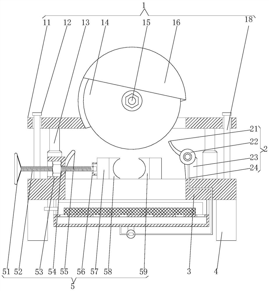
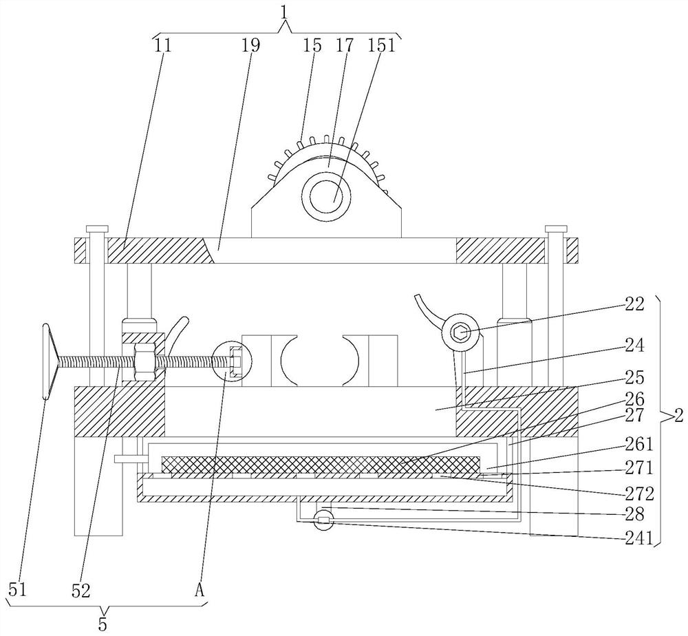
[0026] see Figure 1-5 , the present invention provides a technical solution: a processing device for mechanical lower limbs, including a cutting mechanism 1, a cooling chip removal mechanism 2, an operating table 3, a support plate 4 and a fixing mechanism 5, and the left and right sides of the bottom of the operating table 3 are fixed Connect the top of the support plate 4, the top of the console 3 is fixedly connected to the bottom of the cutting mechanism ...


PUM


Abstract

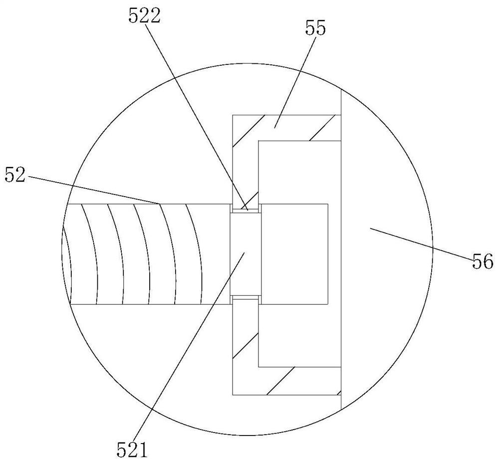
The invention discloses a mechanical lower limb machining device comprising a cutting mechanism, a cooling and scrap removing mechanism, an operation table, a supporting plate and a fixing mechanism,the left side and the right side of the bottom of the operation table are fixedly connected with the top of the supporting plate, and the top of the operation table is fixedly connected with the bottom of the cutting mechanism. The right side of the top of the operation table is fixedly connected with the middle of the cooling and scrap removing mechanism in the cutting mechanism, and the top of the operation table is fixedly connected with the bottom of the fixing mechanism at the left side of the cooling and scrap removing mechanism. According to the mechanical lower limb machining device, amechanical lower limb part needing to be machined and cut is placed between a movable clamping plate and a fixed clamping plate, a threaded rod is rotated by rotating a handle, the movable clamping plate can be effectively close to the fixed clamping plate through cooperation of a connecting piece and a nut, the purpose of clamping and fixing the mechanical lower limb part through the movable clamping plate and the fixed clamping plate is effectively achieved, and therefore the problem that effective and rapid fixing cannot be achieved in the mechanical lower limb machining process can be effectively solved.

Description

technical field [0001] The invention relates to the technical field of mechanical lower limbs, in particular to a processing device for mechanical lower limbs. Background technique [0002] Machinery is a tool device that can help people reduce the difficulty of work or save labor. Items such as chopsticks, brooms, and tweezers can all be called machines, and they are simple machines. A complex machine is composed of two or more simple machines. These more complex machines are usually called machines. From the point of view of structure and motion, there is no difference between a mechanism and a machine, and it is generally called a machine. [0003] Due to various reasons in social life, some people's lower limbs cannot be used normally. Therefore, a mechanical lower limb has been designed, but the existing mechanical lower limb processing and cutting device cannot effectively perform fast and safe cutting during the cutting process. Cutting cannot achieve effective fas...

Claims


Application Information

Patent Timeline
Patent Type & Authority Applications(China)
IPC IPC(8): B23D19/08B23Q3/06B23Q11/00B23Q11/10
CPCB23D19/08B23Q3/06B23Q11/0042B23Q11/10
Inventor 朱璋
Owner 德清博发智能科技有限公司
Why Eureka
Eureka Blog
Learn More