
Device and method for assembling piston pin hole bushing

A piston pin hole and bushing technology, which is applied in the direction of metal processing, metal processing equipment, manufacturing tools, etc., can solve the problems of bushing assembly stuck and scrapped, large assembly position error, reduced assembly clearance, etc., and achieve large assembly clearance , High accuracy of assembly position, small effect of heat absorption expansion

Pending Publication Date: 2021-01-15
成都银河动力有限公司
View PDF0 Cites 1 Cited by
  • Summary
  • Abstract
  • Description
  • Claims
  • Application Information

AI Technical Summary

Problems solved by technology

For pure manual assembly, there are problems of large assembly position error and low assembly efficiency; for the automatic assembly fixture method used in the industry, in the assembly process, it is also necessary to manually install the frozen bushing on the assembly fixture before assembly , in the process of manual installation of the frozen bushing, the bushing will absorb heat and expand, resulting in a rapid reduction in the assembly gap. This method has the problem of being stuck in assembly and scrapping the bushing with a relatively large design interference. If the gap is too small and the assembly tool is forcibly pressed in, the mating surface of the bush and the pin hole will be scratched, causing the bush to fail when the engine is running

Method used


Image

  • Device and method for assembling piston pin hole bushing
  • Device and method for assembling piston pin hole bushing
  • Device and method for assembling piston pin hole bushing

Examples


Embodiment Construction

[0034] The present invention will be further described below in conjunction with the accompanying drawings, but the protection scope of the present invention is not limited to the following description.

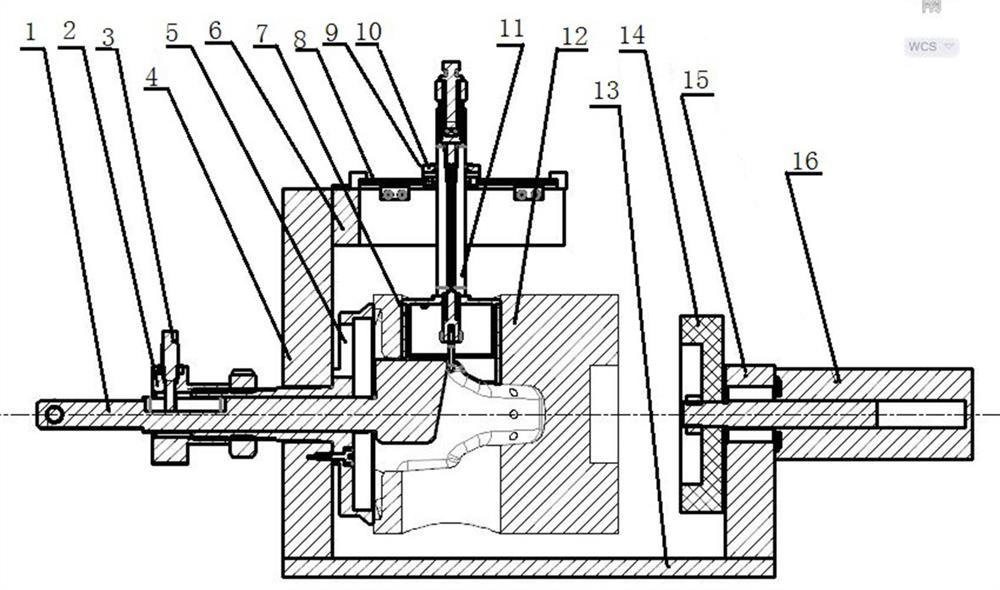
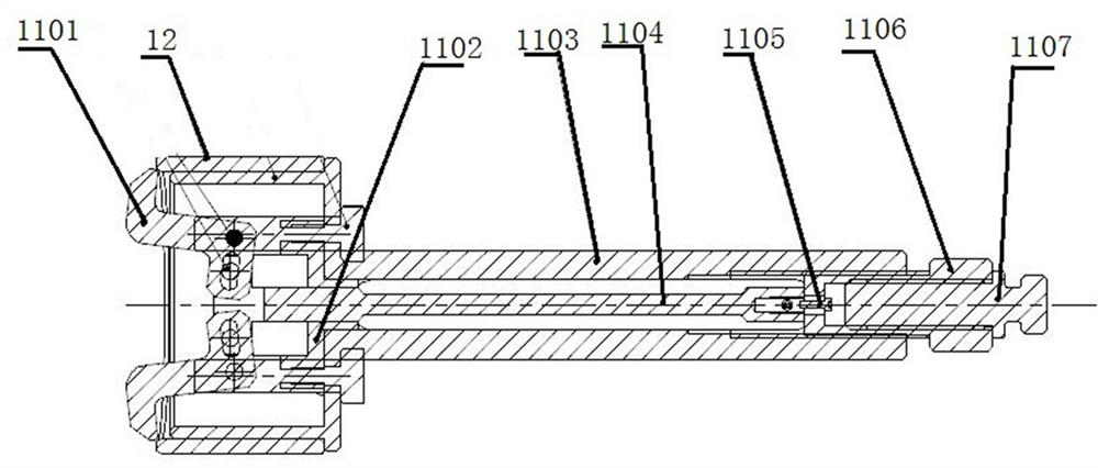
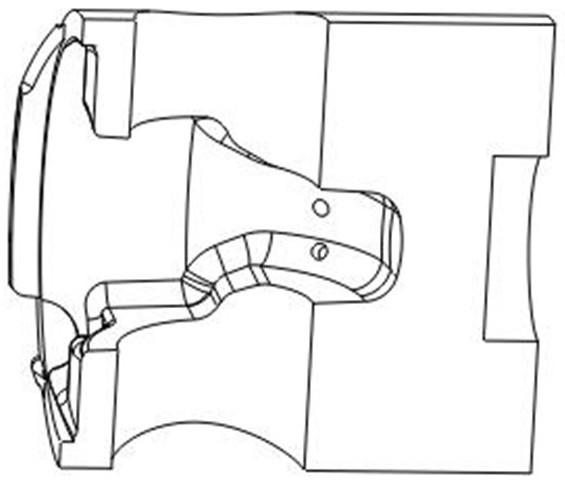
[0035] Such as Figure 1-Figure 4 As shown, a piston pin hole bushing assembly device is used for assembling the bushing 7 on the pin hole on the engine piston 12. One end of the piston 12 is provided with a countersunk cavity, and the countersunk cavity is arranged along the side of the piston 12. The axial direction is symmetrical, and the pin hole runs through the countersunk cavity along the direction perpendicular to the axial direction of the piston 12, including the mounting seat, the fixing device, the clamping device of the bushing 7 and the angle positioning device; wherein:

[0036] The mounting seat includes a base 13 and a support body a4 and a support body b15 respectively fixed at both ends of the base 13, and the fixing device includes a clamping cylinder 16 a...


PUM


Abstract

The invention relates to a device and a method for assembling a piston pin hole bushing and relates to the field of machine manufacturing. The device and the method are used for assembling a bushing in a pin hole in an engine piston. The device comprises a mounting seat, a fixing device, a bushing clamping device and an angle positioning device. The mounting seat comprises a base, a supporting body a and a supporting body b, wherein the supporting body a and the supporting body b are fixed to the two ends of the base correspondingly. The fixing device comprises a clamping cylinder and an ejection tray. The piston is arranged between the supporting body a and the supporting body b, and the two end faces of the piston are attached to the supporting body a and the supporting body b correspondingly. The lining clamping device comprises a clamp and a moving device, the moving device is fixed to the supporting body a, and the clamp is connected with the moving device. The angle positioning device comprises an angle positioning rod, a limiting adjusting sleeve and a limiting pin. When the bushing with the magnitude of interference larger than or equal to 0.1 is assembled, the assembling efficiency is higher, the assembling quality is better, the defective product rate is lower under the same condition, the overall structure is simple, and safety and reliability are achieved.

Description

technical field [0001] The invention relates to the field of mechanical manufacturing, in particular to a bushing device for assembling a piston pin hole and a method for assembling the bushing. Background technique [0002] In the industry, in order to improve the bearing capacity of the piston pin hole and prevent the pin hole from cracking, copper bushings are usually embedded in the piston pin hole. At present, the piston pin hole bushing assembly of internal combustion engines usually adopts a cold installation or a combination of cold and hot installation. For pure manual assembly, there are problems of large assembly position error and low assembly efficiency; for the automatic assembly fixture method used in the industry, in the assembly process, it is also necessary to manually install the frozen bushing on the assembly fixture before assembly , in the process of installing the bushing after manual contact with the frozen bushing, the bushing will absorb heat and e...

Claims


Application Information

Patent Timeline
Patent Type & Authority Applications(China)
IPC IPC(8): B23P19/00B23P11/02
CPCB23P19/00B23P11/025
Inventor 温志高郭燕清彭明诚袁映中胡少强陈祥
Owner 成都银河动力有限公司
Learn More