

Grouting structure of prestressed concrete stiffening beam long duct and construction method thereof
A technology of prestressed and stiffened beams, applied in the field of engineering, can solve problems such as inability to obtain effective guarantees, and achieve the effects of convenient construction organization, good effect and remarkable benefits
- Summary
- Abstract
- Description
- Claims
- Application Information
AI Technical Summary
Problems solved by technology
Method used
Image

Examples
Embodiment 1
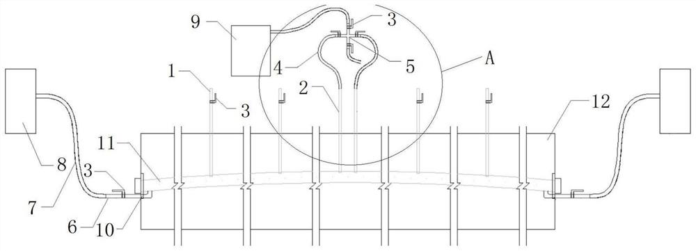
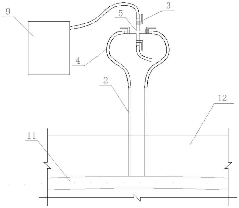
[0033] Such as Figure 1-Figure 2 As shown, a grouting structure for long channels of prestressed concrete stiffened beams, including a grout filling pipe 1, a grout discharge pipe 2, a grout stop valve 3, a transparent steel wire hose 4, a four-way connector 5, a grouting device, a pumping Vacuum machine 9, super long prestressed tunnel 11 and concrete stiffened beam 12;
[0034] The concrete stiffening beam 12 is provided with a super-long prestressed channel 11, and both ends of the super-long prestressed channel 11 are provided with grouting holes 10, and the upper ends of the grout filling pipe 1 and the grout discharge pipe 2 are both communicate with the outside world, the lower ends of the grout filling pipe 1 and the grout discharge pipe 2 pass through the concrete stiffening beam 12 and communicate with the super-long prestressed tunnel 11, and the grout filling pipe 1 is provided with a stop Slurry valve 3;
[0035] There are multiple grout filling pipes 1, two gr...
Embodiment 2
[0047] A construction method for a grouting structure of a prestressed concrete stiffened beam long channel, comprising the following steps:
[0048] Step 1: Before vacuuming, close all the slurry stop valves 3, and when vacuuming, open the four stop valves 3 on the four-way connector 5, and then close the slurry stop valves connected to the external interface 3, and open described vacuum pumping machine 9 to carry out vacuuming;
[0049] Step 2: when the vacuum pressure reaches the control value, simultaneously open the two grouting machines 8 and open the grouting stop valve 3 on the grouting connecting pipe 6 to grout;
[0050] Step 3: During the grouting process, sequentially open the grout stop valve 3 on the grout filling pipe 1 from both ends of the concrete stiffening beam 12 toward the mid-span direction, and check the grouting situation, and wait for the grout to flow from the mid-span When the grout filling pipe 1 flows out to a certain transparent steel wire hose 4,...
PUM
| Property | Measurement | Unit |
|---|---|---|
| Length | aaaaa | aaaaa |
Abstract
Description
Claims
Application Information