Terahertz spectrum measurement device, measurement method and application thereof
A measurement method and terahertz technology, applied in measurement devices, measuring electrical variables, using optical devices, etc., can solve problems such as increasing test time and inability to eliminate deviations
- Summary
- Abstract
- Description
- Claims
- Application Information
AI Technical Summary
Problems solved by technology
Method used
Image
Examples
Embodiment 1
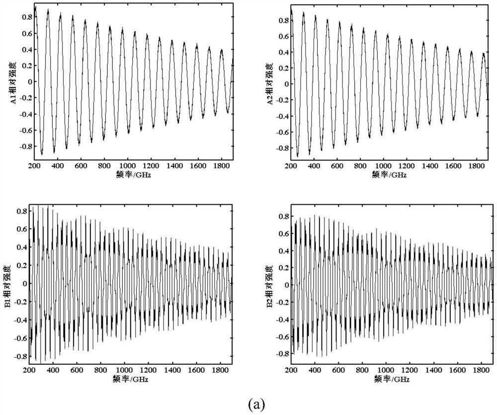
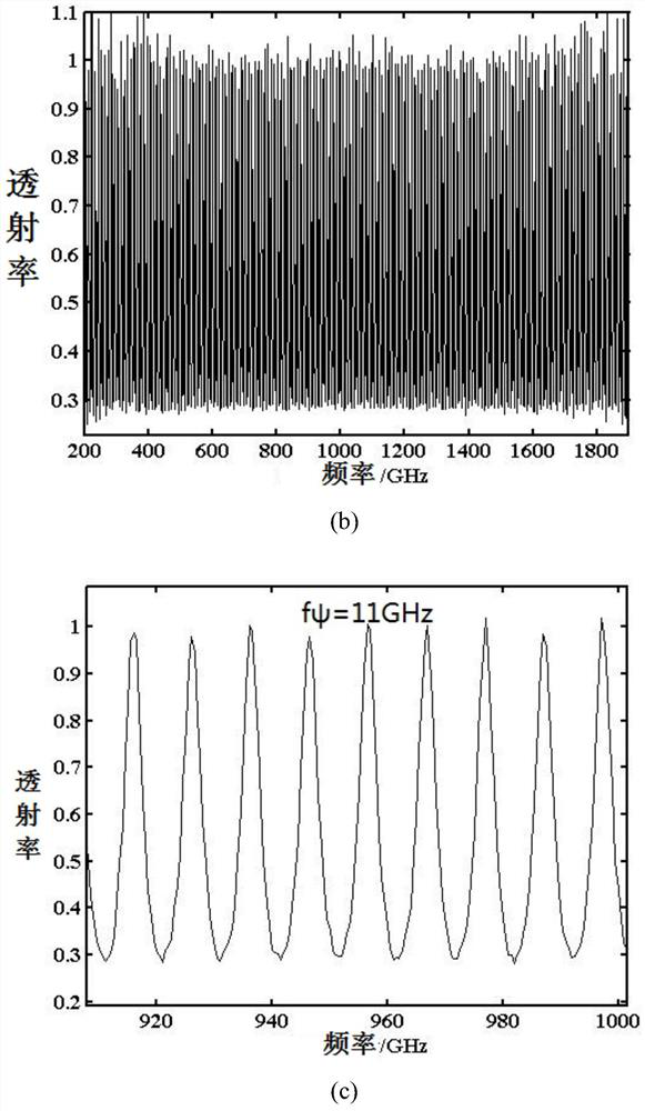
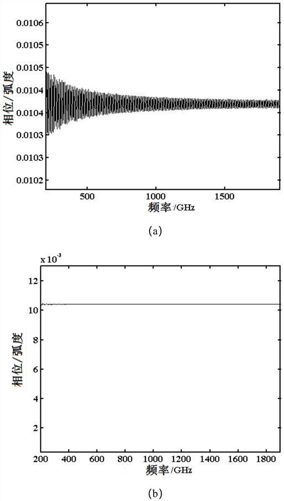
[0072] Schematic representation of measuring device and method of the present invention picture Such as Figure 4 As shown, the device includes: a difference frequency laser source 4003 with two frequency differences in the terahertz band, a terahertz transmitting antenna 4004 and a receiving antenna 4009, a bias voltage circuit 4002, terahertz parabolic mirrors 4005 and 4012, and signal output acquisition Circuit 4001. The terahertz parabolic mirror 4005 and the terahertz transmitting antenna 4004 form the transmitting end 4013 , and the terahertz parabolic mirror 4012 and the terahertz transmitting antenna 4009 form the detecting end 4014 . If a precision translation platform is selected to adjust the phase, the transmitting end 4013 and the detection end or 4014 are installed on a precise translation platform 4015, or the transmitting end 4013 or the detection end 4014 are respectively installed on two translation platforms 4015 ( picture (not shown in ), used to adjust t...
Embodiment 2
[0101] Schematic representation of measuring device and method of the present invention picture Such as Figure 4 As shown, the device includes: a difference frequency laser source 4003 with two frequency differences in the terahertz band, a terahertz transmitting antenna 4004 and a receiving antenna 4009, a bias voltage circuit 4002, terahertz parabolic mirrors 4005 and 4012, and signal output acquisition Circuit 4001. The terahertz parabolic mirror 4005 and the terahertz transmitting antenna 4004 form the transmitting end 4013 , and the terahertz parabolic mirror 4012 and the terahertz transmitting antenna 4009 form the detecting end 4014 . If the delay line (delay line) for adjusting the optical path is selected, it is located at the position of 4011 or 4010, the adjustment accuracy of the optical path reaches 1.5nm, and the total amount of adjustment is 1500nm. Sample 4006 is high-resistance silicon with a resistivity greater than 10kΩ·cm and a thickness of 2.16mm. The ...
Embodiment 3
[0122] Schematic representation of measuring device and method of the present invention picture Such as Figure 4 As shown, the device includes: a difference frequency laser source 4003 with two frequency differences in the terahertz band, a terahertz transmitting antenna 4004 and a receiving antenna 4009, a bias voltage circuit 4002, terahertz parabolic mirrors 4005 and 4012, and signal output acquisition Circuit 4001. The terahertz parabolic mirror 4005 and the terahertz transmitting antenna 4004 form the transmitting end 4013 , and the terahertz parabolic mirror 4012 and the terahertz transmitting antenna 4009 form the detecting end 4014 . The electro-optic modulator is selected, the adjustment accuracy of the phase is 0.004 radians, and the total amount of adjustment is 4 radians. Sample 4006 is silicon thickness 1mm.
[0123] The difference-frequency laser emitted by the difference-frequency laser source 4003 is combined and split into two beams by the beam combiner 40...
PUM
| Property | Measurement | Unit |
|---|---|---|
| thickness | aaaaa | aaaaa |
| electrical resistivity | aaaaa | aaaaa |
| thickness | aaaaa | aaaaa |
Abstract
Description
Claims
Application Information
 - R&D
- Intellectual Property
- Life Sciences
- Materials
- Tech Scout
- Unparalleled Data Quality
- Higher Quality Content
- 60% Fewer Hallucinations
Browse by: Latest US Patents, China's latest patents, Technical Efficacy Thesaurus, Application Domain, Technology Topic, Popular Technical Reports.
© 2025 PatSnap. All rights reserved.Legal|Privacy policy|Modern Slavery Act Transparency Statement|Sitemap|About US| Contact US: help@patsnap.com


