
Eureka
For R&D, Eureka makes reading and utilizing patents & technical documents easy.
Eureka AIR
Designed for self-driven R&D workflows. Generate viable solutions, solve complex R&D challenges, empower your innovation with AI.

Eureka Materials
Designed for material experts only. Revolutionize your material R&D, from search, analyze, to developing new materials.

TechResearch
Generate reliable direction feasibility study reports for your R&D in just a few steps.

TechSeek
Discover and master advanced knowledge NOW. Basics, ideas, possibilities, all at once.

TechMind
As an expert in R&D Theories, TechMind can generates customized viable solutions instantly.

TechRisk
Analyze your overall solution with one click, know your potential R&D risks in advance.

TechMonitor
Get weekly tech updates, stay abreast of the latest tech innovations and key insights.
Tool turret
A technology of tool turret and tool disc, which is applied in the direction of manufacturing tools, driving devices, metal processing mechanical parts, etc., can solve the problems of increasing processing costs and heavy workload of operators, and achieves stable replacement, high flexibility and low cost. Effect
- Summary
- Abstract
- Description
- Claims
- Application Information
AI Technical Summary
Problems solved by technology
Method used
Image

Examples
Embodiment Construction
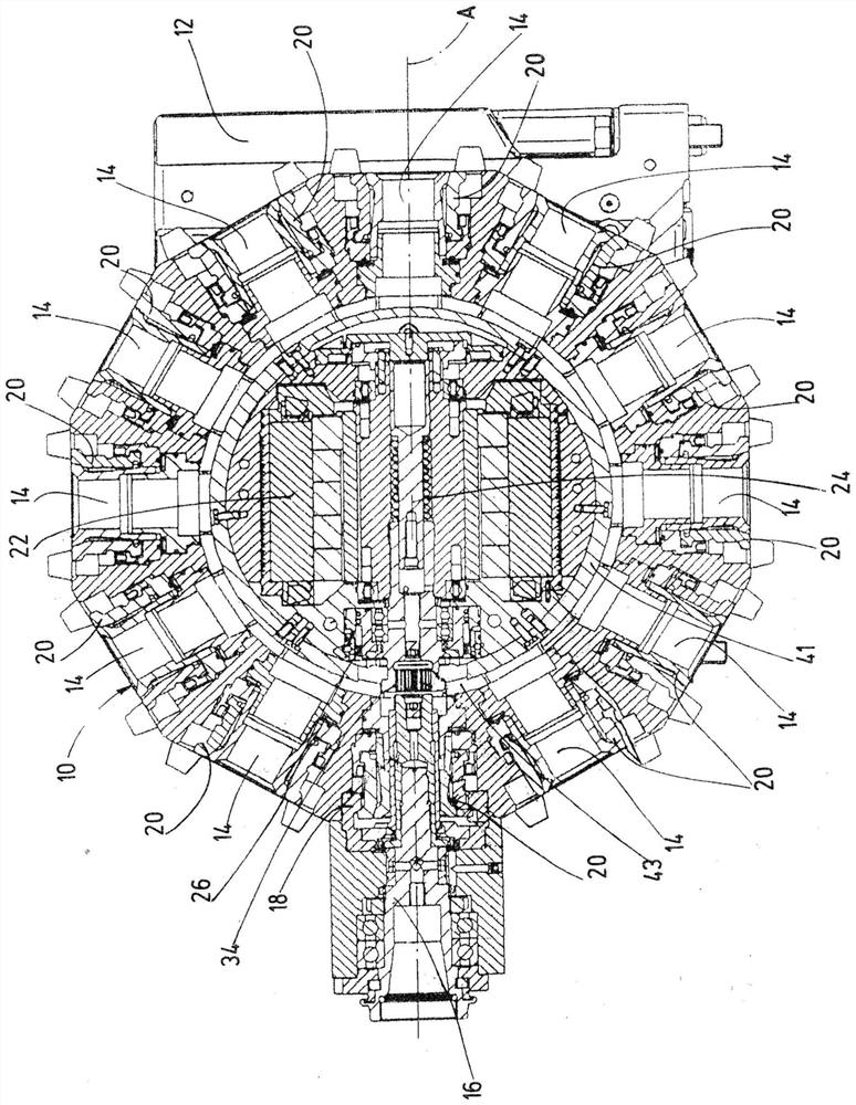
[0022] figure 1 An exemplary tool disk 10 of a tool turret according to the invention is shown. The tool turret is provided in particular for use in a machine tool and can be connected to the machine tool via the base body 12 . The tool disk 10 is arranged pivotably relative to the turret axis on a base body 12 and has a plurality—twelve in the exemplary embodiment shown—receptacles 14 on the outer peripheral side. exist figure 1 The middle tool spindle 16 is part of a tool carrier 18 designed as a spindle head. The tool holder 18 has the conventional design of a spindle head as disclosed, for example, in DE 10121694 A1 and the machining tool accommodated therein is not shown in the figures. The abutment 18 received in the receptacle 14 is located in the working position of the tool disc 10 relative to figure 1 Orientation of the drawings at the 9 o'clock position. A fastening device 20 is assigned to each receptacle 14 in order to fasten the corresponding holder 18 on th...
PUM
 Abstract
Description
Claims
Application Information
 - R&D Engineer
- R&D Manager
- IP Professional
- Industry Leading Data Capabilities
- Powerful AI technology
- Patent DNA Extraction
Browse by: Latest US Patents, China's latest patents, Technical Efficacy Thesaurus, Application Domain, Technology Topic, Popular Technical Reports.
© 2024 PatSnap. All rights reserved.Legal|Privacy policy|Modern Slavery Act Transparency Statement|Sitemap|About US| Contact US: help@patsnap.com