
Self-aligned layer patterning

A patterning and self-alignment technology, applied in the direction of semiconductor devices, electrical components, circuits, etc., can solve problems such as exceeding, and achieve the effect of reducing the risk of collapse

Pending Publication Date: 2021-01-19
INTERUNIVERSITAIR MICRO ELECTRONICS CENT (IMEC VZW)
View PDF0 Cites 0 Cited by
  • Summary
  • Abstract
  • Description
  • Claims
  • Application Information

AI Technical Summary

Problems solved by technology

However, forming lines with narrower widths is beyond the capabilities of current photolithography processes

Method used


Image

  • Self-aligned layer patterning
  • Self-aligned layer patterning
  • Self-aligned layer patterning

Examples


Embodiment Construction

[0035] The present invention will be described with respect to particular embodiments and with reference to certain drawings but the invention is not limited thereto but only by the claims. The drawings described are only schematic and non-limiting. In the drawings, the size of some of the elements may be exaggerated and not drawn on scale for illustrative purposes. The dimensions and relative dimensions do not correspond to true reductions to the practice of the invention.

[0036] Furthermore, the terms first, second and third, etc. in the description and claims are used to distinguish similar elements, and not necessarily used to describe sequential order in time, space, arrangement or any other manner. It is to be understood that the terms so used are interchangeable under appropriate circumstances and that the embodiments of the invention described herein are capable of operation in other sequences than described or illustrated herein.

[0037] Also, the terms top, bottom...


PUM


Abstract

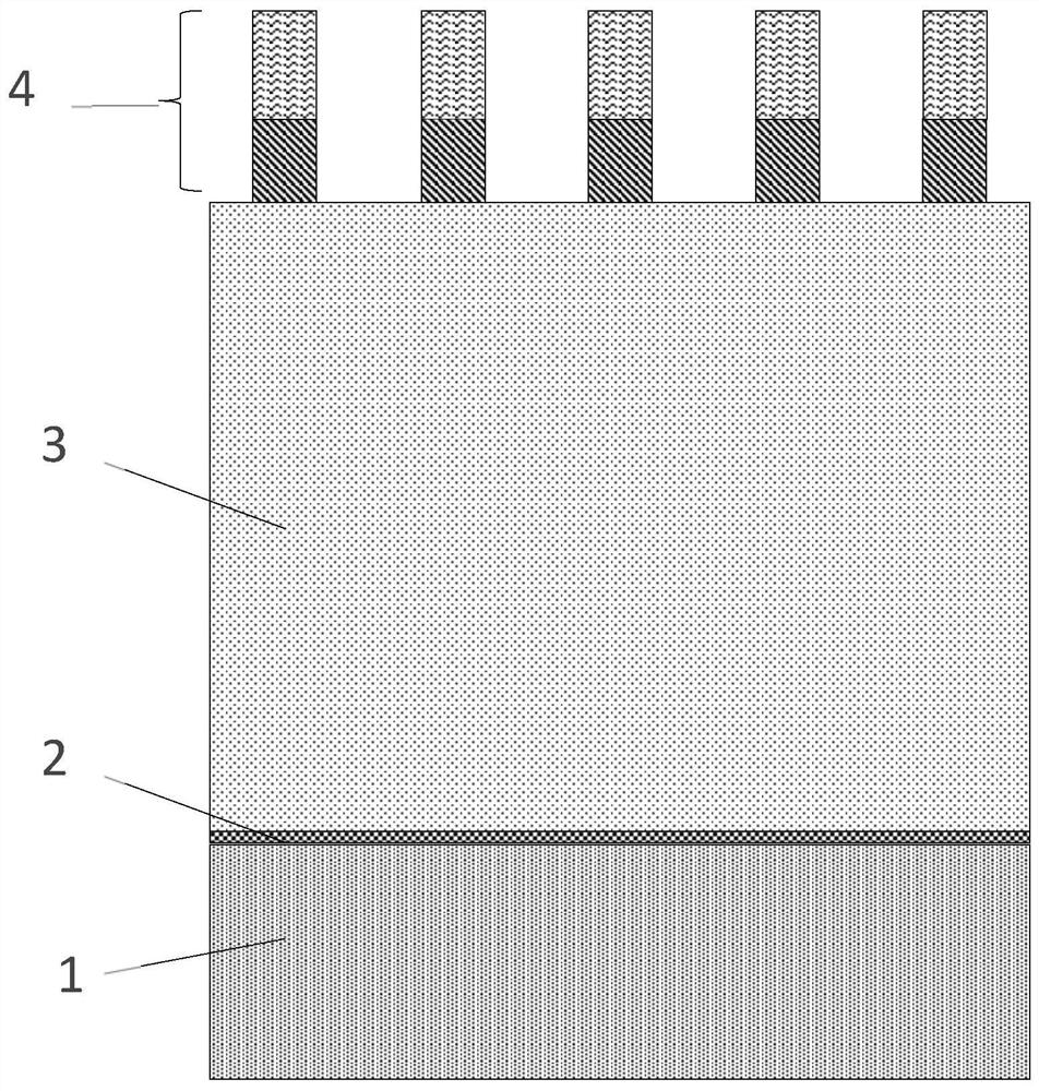
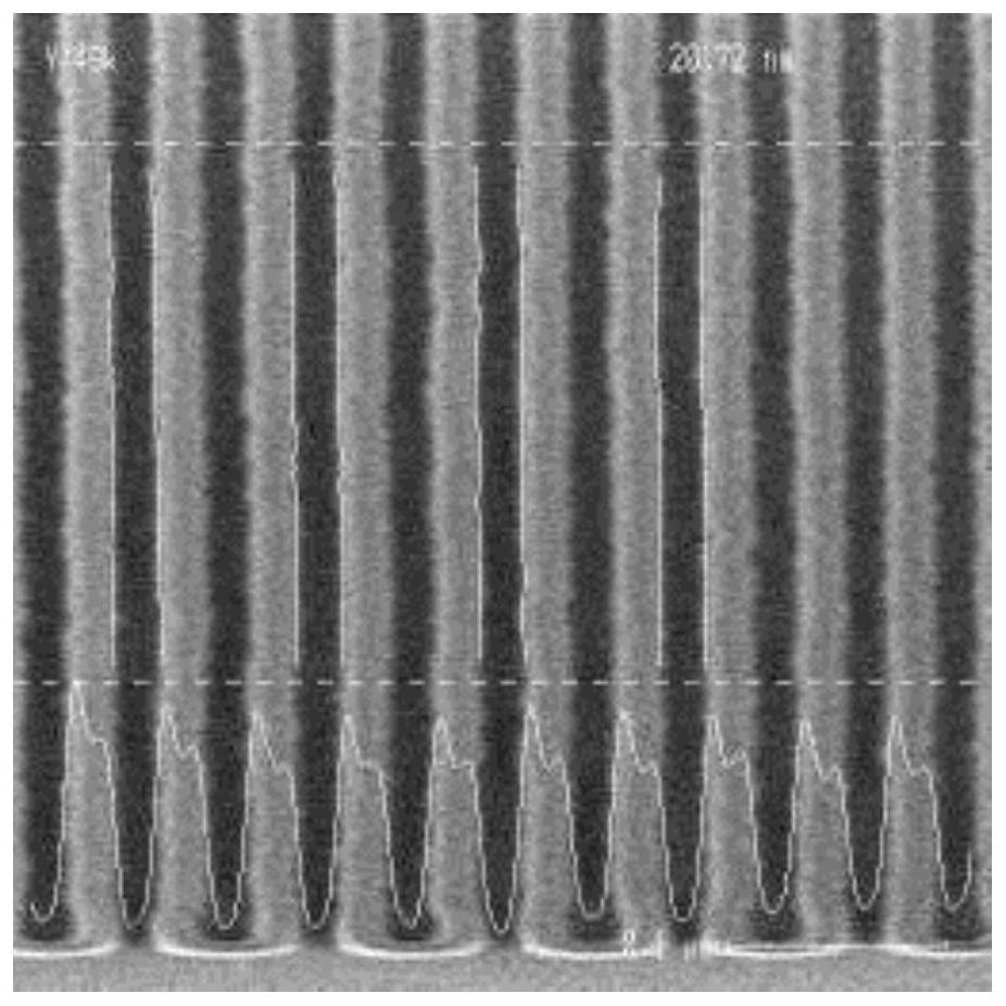
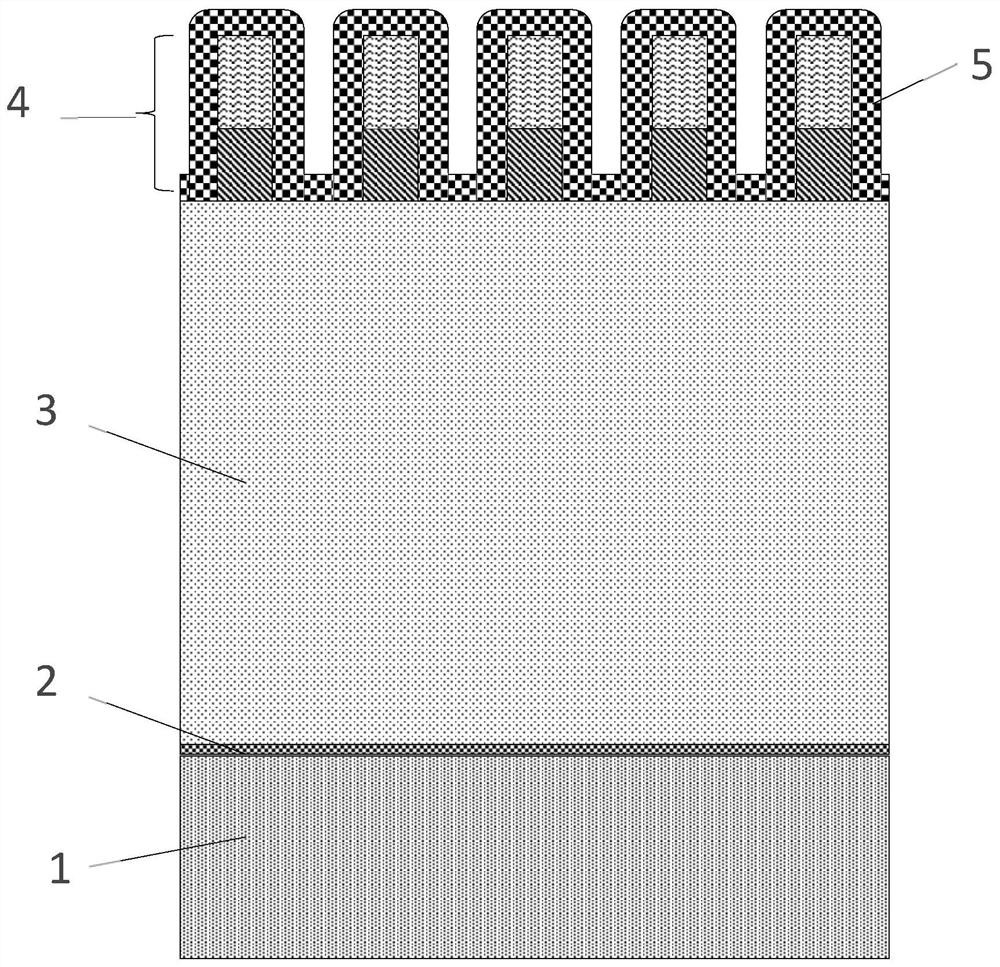
A method comprising the steps of: a. forming, by self-aligned multiple patterning, a first pattern of regularly spaced mandrels (4) on a layer (3) to be patterned; b. subsequently, forming hard mask spacers (5) on sidewalls of the mandrels (4), thereby forming a second pattern formed of assemblies (4, 5) comprising a mandrel (4) and hard mask spacers (5) on sidewalls thereof, and c. subsequently,etching the second pattern in the layer (3) to be patterned.

Description

technical field [0001] The present invention relates to the field of layer patterning, and more particularly to the patterning of parallel lines in semiconductor materials, especially for the formation of Fin Field Effect Transistor (FinFET) gates. Background technique [0002] When a pattern of parallel lines in a semiconductor material is desired, a typical procedure is to cover the semiconductor with a hard mask to form parallel lines of photoresist material by photolithography on the hard mask, followed by transfer of these lines and eventually into the semiconductor material. [0003] For example, this process permits the formation of 42nm wide lines separated by 42nm wide spaces. However, forming lines of narrower width is beyond the capabilities of current photolithography processes. In order to increase the density of lines, a line multiplying process such as SAMP (Self-Aligned Multiple Patterning) can be used. The simplest SAMP process is SADP (Self-Aligned Doubl...

Claims


Application Information

Patent Timeline
IPC IPC(8): H01L21/336H01L29/78H01L21/308
CPCH01L29/66795H01L29/7855H01L21/308H01L21/3085H01L21/0337H01L29/66545H01L21/823431H01L21/0274H01L29/41791H01L29/6681H01L29/785
Inventor B·T·曾Y·K·萧J·博迈尔斯
Owner INTERUNIVERSITAIR MICRO ELECTRONICS CENT (IMEC VZW)
Learn More