Supercharge Your Innovation With Domain-Expert AI Agents!

Cleaning machine

A washing machine and washing cavity technology, which is applied in the field of washing machines for washing dishes, fruits and vegetables, can solve the problems of loss, dead corners in washing dishes, uneven tableware placement, etc., so as to reduce production costs, simplify the overall structure, Improve the effect of cleaning

Active Publication Date: 2021-01-22
NINGBO FOTILE KITCHEN WARE CO LTD
View PDF10 Cites 6 Cited by
  • Summary
  • Abstract
  • Description
  • Claims
  • Application Information

AI Technical Summary

Problems solved by technology

This results in a large amount of water vapor remaining in the washing chamber after cleaning. After the water vapor condenses, it will accumulate on the surface of the tableware. The dripping water not only affects the user experience, but also easily breeds bacteria
Although the existing washing machine also introduces gas to dry dishes, it is mainly introduced from the side wall, and the convection and diffusion in a relatively natural state are realized by using the wind speed of the inlet. However, due to the uneven placement of tableware, the wind mainly Concentrated at the air inlet of the tank, and with the occurrence of eddy currents, a large amount of energy is lost, and finally the distribution of hot air in the entire tank is very uneven, and the drying effect at the corners far away from the air inlet and the door panel is relatively poor. Difference
[0005] In addition, because the existing washing machine uses a bottom-up spray method for cleaning, when the dishes are placed unevenly or there are many dishes, the dishes on the top are likely to have dead spots for cleaning, resulting in unsatisfactory cleaning results

Method used


Image

  • Cleaning machine
  • Cleaning machine
  • Cleaning machine

Examples


Embodiment Construction

[0028] The present invention will be further described in detail below in conjunction with the accompanying drawings and embodiments.

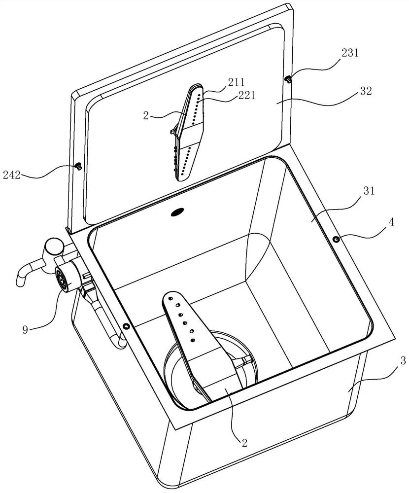
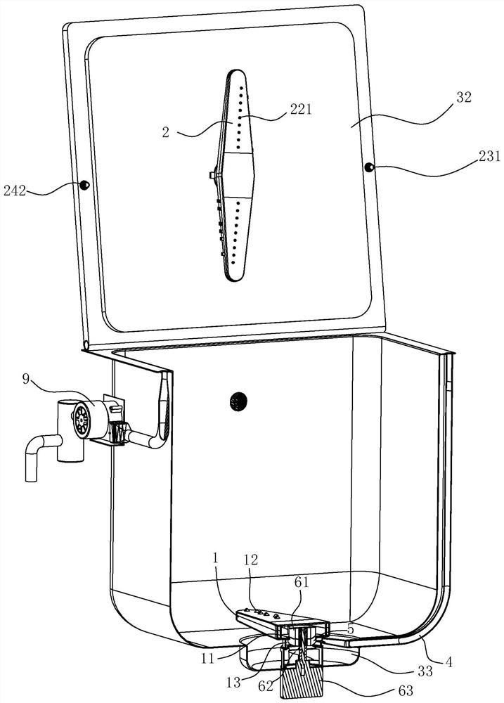
[0029] Such as Figure 1-10 As shown, the washing machine of this embodiment includes a box body 3, a first spray arm 1 and a second spray arm 2, and the box body 3 has a washing chamber 31 and a top opening on which a door body 32 is installed. The first spray arm 1 is rotatably arranged at the bottom of the washing chamber 31 and is used for spraying the water at the bottom of the tank 3 upwards, and the second spray arm 2 is rotatably arranged on the inner wall of the door body 32 .

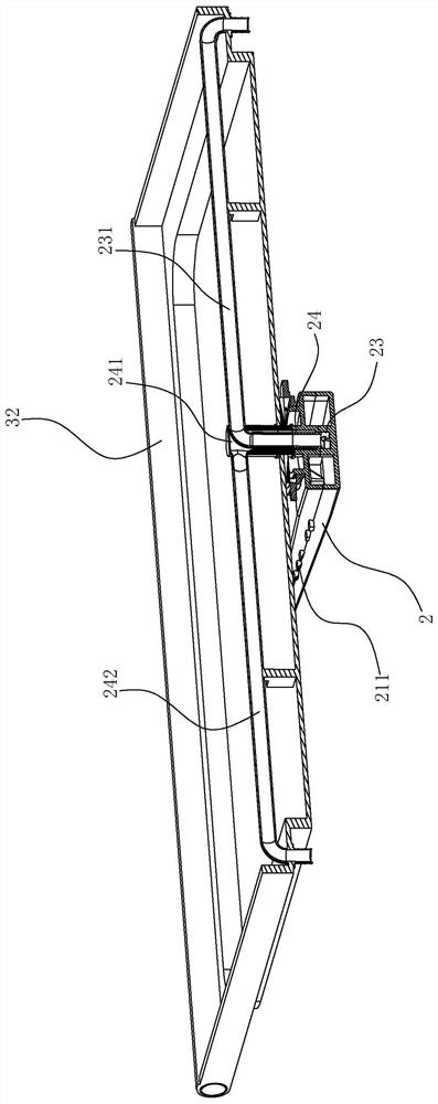
[0030] Such as Figure 4-10 As shown, the second spray arm 2 has an upper layer 2a and a lower layer 2b, the upper layer is provided with a gas channel 21, and the lower layer is provided with a liquid channel 22, and the gas channel 21 and the liquid channel 22 are relatively independent. The top wall and side wall of the second spray arm 2 are provided wit...


PUM


Abstract

The invention relates to a cleaning machine. The cleaning machine comprises a box body and a first spraying arm, the box body is provided with a washing cavity, the first spraying arm is arranged at the bottom of the washing cavity and used for spraying water at the bottom of the box body upwards, the cleaning machine further comprises a second spraying arm arranged at the top of the washing cavity, and a gas flow channel and a liquid flow channel which are relatively independent up and down are formed in the second spraying arm. The top wall and / or the side wall of the second spraying arm are / is provided with gas spraying holes communicated with the gas flow channel, and the bottom wall of the second spraying arm is provided with water spraying holes communicated with the liquid flow channel. The second spraying arm can be matched with the first spraying arm to achieve up-down two-way spraying cleaning, so that cleaning dead corners are eliminated, and the cleaning effect is improved;the second spraying arm can also convey gas into the washing cavity through gas spraying holes in the top wall and / or the side wall of the second spraying arm, and the gas is dispersed along the inner top wall of the washing cavity and then can be quickly dispersed everywhere of the washing cavity, so that drying dead angles are eliminated, and the drying effect is improved; a spraying structureand an air inlet structure are integrated on the second spraying arm, so that the whole structure is simplified, and the production cost is reduced.

Description

technical field [0001] The invention relates to the technical field of household appliances, in particular to a washing machine for washing dishes, fruits and vegetables. Background technique [0002] A dishwasher is a device that sprays cold or hot water onto dishes to remove dirt adhering to the dishes and cleans the dishes. The dishes are placed in the dish frame in the dishwashing cabinet. A general dishwasher includes a pump and a nozzle for spraying washing water, a heater for generating hot water, and the like. Such a dishwasher usually requires its own independent shell and independent components, so the general dishwasher is relatively large in size and is not suitable for families with a large population and a small living area per capita. Therefore, in many families, Dishwasher use is also not very common. [0003] In order to save space and expand the scope of application, there have been many sink-type washing machine designs, that is, the existing sink is con...

Claims


Application Information

Patent Timeline
IPC IPC(8): A47L15/22A47L15/42A47L15/48
CPCA47L15/22A47L15/42A47L15/428A47L15/486A47L15/4217A47L2601/02
Inventor 侯富龙
Owner NINGBO FOTILE KITCHEN WARE CO LTD
Features
  • R&D
  • Intellectual Property
  • Life Sciences
  • Materials
  • Tech Scout
  • Unparalleled Data Quality
  • Higher Quality Content
  • 60% Fewer Hallucinations
Learn More