Nano-bubble and micron-bubble gradient generator

A technology of micro-bubbles and nano-bubbles, applied in the direction of fluid mixers, transportation and packaging, chemical instruments and methods, etc., can solve the problems of complex equipment, long bubble generation cycle, high energy consumption, etc., and achieve the effect of simple structure

Pending Publication Date: 2021-01-22
CHINA UNIV OF MINING & TECH
View PDF0 Cites 0 Cited by
  • Summary
  • Abstract
  • Description
  • Claims
  • Application Information

AI Technical Summary

Problems solved by technology

However, the above-mentioned generation methods have disadvantages such as high energy consumption, complicated equi

Method used


Image

  • Nano-bubble and micron-bubble gradient generator

Examples


Embodiment Construction

[0015] The following will clearly and completely describe the technical solutions in the embodiments of the present invention with reference to the accompanying drawings in the embodiments of the present invention. Obviously, the described embodiments are only some, not all, embodiments of the present invention. Based on the embodiments of the present invention, all other embodiments obtained by persons of ordinary skill in the art without making creative efforts belong to the protection scope of the present invention.

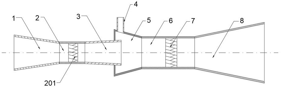
[0016] The present invention provides such figure 1 A nanobubble and microbubble gradient generator shown includes a nozzle 1, a first mixing section 2, a first self-driven rotary impeller 201, a first diverging section 3, an air suction chamber 5, a second mixing section 6, The second self-driven rotary impeller 7, the second diverging section 8 and the gas phase inlet pipe 4, the nozzle 1, the first mixing section 2, the first diverging section 3, the suctio...


PUM


Abstract

The invention discloses a nano-bubble and micron-bubble gradient generator which comprises a nozzle, a first mixing section, a first self-driven rotating impeller, a first diverging section, an air suction chamber, a second mixing section, a second self-driven rotating impeller, a second diverging section and a gas phase inlet pipe. The nozzle, the first mixing section, the first diverging section, the air suction chamber, the second mixing section and the second diverging section are sequentially connected through threads or flanges or in a welding mode. Nano bubbles are separated out at thefront half part of the device by utilizing a reinforced hydrodynamic cavitation effect, micron bubbles are formed at the rear half part of the device by adopting a jet air entraining mode, and the size and the concentration of the separated nano bubbles are adjusted by changing the rotating speed of the first self-driven rotating impeller; the second self-driven rotating impeller can change the turbulence intensity of a gas-liquid two-phase flow field so as to influence the size and dispersion degree of bubbles, and the device is simple in structure, low in energy consumption and beneficial toengineering of the device.

Description

technical field [0001] The invention relates to the field of bubble generators, in particular to a nano-bubble and micro-bubble gradient generator. Background technique [0002] Micro-nano bubbles have the advantages of large specific surface area, long residence time and high mass transfer efficiency, and have good application effects in mineral flotation, sewage treatment, agricultural breeding, biomedicine and other fields. At present, the main ways to generate micro-nano bubbles are: electrolysis method, ultrasonic method, pressurized dissolved air method, hydrodynamic cavitation method, and photocatalytic method. However, the above-mentioned production methods have disadvantages such as high energy consumption, complicated equipment, and long bubble generation cycle, which limit the wide application of micro-nano bubbles in industrialization. Contents of the invention [0003] Aiming at the technical deficiencies mentioned above, the object of the present invention i...

Claims


Application Information

Patent Timeline
IPC IPC(8): B01F3/04B01F5/02B01F15/00B01F5/00
CPCB01F23/233B01F23/2366B01F23/2368B01F23/291B01F2025/912B01F25/28B01F35/32015
Inventor 许恩乐苗真勇陈元龙万克记贺琼琼江晓凤张一昕厉伟
Owner CHINA UNIV OF MINING & TECH
Why Eureka
Try Eureka