Lifting flotation machine for graphite production

A lift-type, flotation machine technology, applied in flotation, solid separation and other directions, can solve the problems of slow material mixing reaction, low device working efficiency, easy adhesion of bubbles on the inner wall of the tank, etc., to reduce the use of power equipment, improve Stirring effect, the effect of optimizing the flotation effect

Inactive Publication Date: 2021-01-22
马丹丹
View PDF0 Cites 2 Cited by
  • Summary
  • Abstract
  • Description
  • Claims
  • Application Information

AI Technical Summary

Problems solved by technology

[0004] The purpose of the present invention is to solve the problems in the prior art that the mixing reaction of materials is slow, the working efficiency of the device is low, and bubbles are easily attached to the inner wall of the tank, and a lifting type flotation machine for graphite production is proposed.

Method used


Image

  • Lifting flotation machine for graphite production
  • Lifting flotation machine for graphite production
  • Lifting flotation machine for graphite production

Examples


Embodiment 1

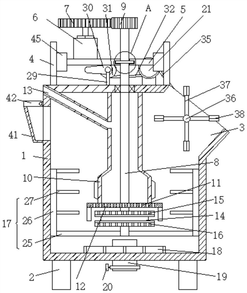
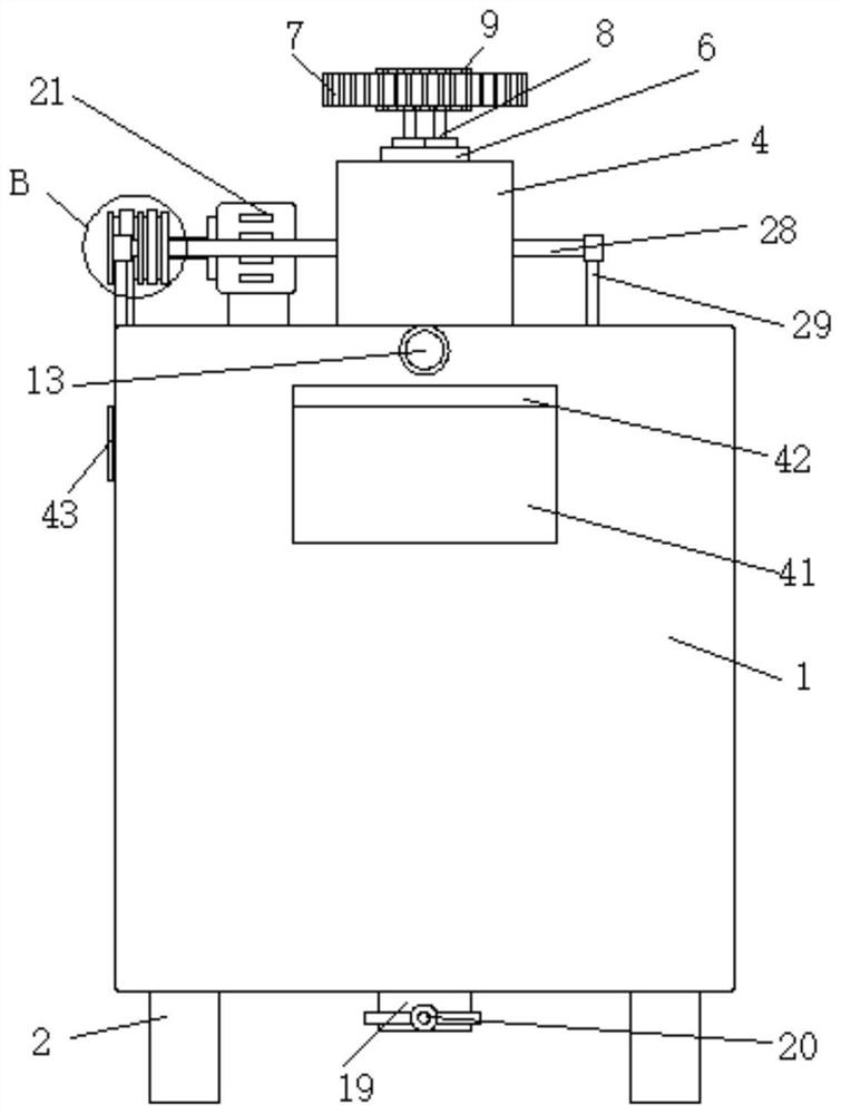
[0031] Embodiment one, such as Figure 1-8As shown, a lifting type flotation machine for graphite production includes a tank body 1, the tank body 1 is cylindrical, the outer bottom surface of the tank body 1 is fixedly connected with a plurality of vertically arranged support columns 2, and the upper end of the tank body 1 is An opening 3 is provided, and the upper surface of the upper wall of the tank body 1 is fixedly connected with two vertically arranged support plates 4, and a bottom plate 5 is horizontally arranged between the two support plates 4, and the bottom plate 5 is slidingly connected with the two support plates 4, The upper surface of the base plate 5 is fixedly connected with the first motor 6, the shaft of the first motor 6 is fixedly connected with the first gear 7 arranged horizontally, and one side of the first motor 6 is vertically provided with a main shaft 8, the main shaft 8 penetrates the base plate 5 and is connected with the The rotation connection...

Embodiment 2

[0032] Embodiment two, such as figure 1 As shown, the stirring mechanism 17 includes a plurality of first connecting rods 25 arranged horizontally, and the plurality of first connecting rods 25 are all fixedly connected to the main shaft 8, and the plurality of first connecting rods 25 are all located below the impeller disc 14, and the plurality of first connecting rods 25 are all fixedly connected to the main shaft 8. The upper surface of one end of the connecting rod 25 away from the main shaft 8 is fixedly connected with a second connecting rod 26, and a plurality of second connecting rods 26 are all vertically arranged, and a plurality of second connecting rods 26 are in contact with the inner wall of the tank body 1. The second connecting rods 26 are all fixedly connected with a plurality of horizontally arranged stirring rods 27, and the plurality of stirring rods 27 are arranged at equal intervals, and the mixing of materials is promoted by the rotating stirring rods 27...

Embodiment 3

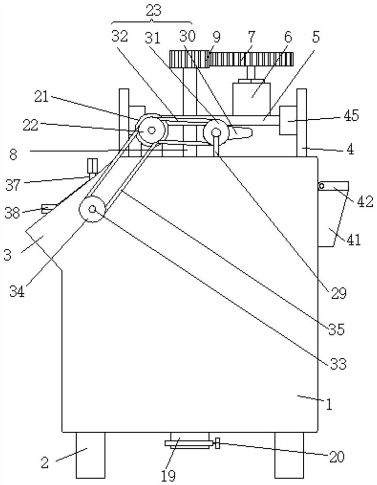
[0033] Embodiment three, such as Figure 1-4 , 6, the elevating mechanism 23 comprises the first rotating shaft 28 that is arranged horizontally, the first rotating shaft 28 two ends all rotate and connect the bracket 29, the two brackets 29 are all vertically arranged, and the bottom ends of the two brackets are all connected to the upper wall of the tank body 1. The upper surface is fixedly connected, the first rotating shaft 28 is fixedly connected with a cam 30, the cam 30 is in contact with the lower surface of the bottom plate 5, the first rotating shaft 28 is fixedly connected with a second pulley 31, and the second pulley 31 is connected to the first pulley through the first belt 32. 22 transmission connection, through the rotation of the cam 30, the bottom plate 5 is driven up and down, and then the first motor 6 and the main shaft 8 are driven to move up and down, so as to realize the lifting and promote the stirring of the stirring rod 27, which is more conducive to ...


PUM


Abstract

The lifting type flotation machine for graphite production comprises a tank body, the tank body is cylindrical, a plurality of vertically-arranged supporting columns are fixedly connected to the outerbottom face of the tank body, an opening is formed in the upper end of one side of the tank body, and two vertically-arranged supporting plates are fixedly connected to the upper surface of the upperwall of the tank body; a bottom plate is horizontally arranged between the two supporting plates; the bottom plate is slidably connected with the two supporting plates; a first motor is fixedly connected to the upper surface of the bottom plate; and a horizontally-arranged first gear is fixedly connected to a shaft of the first motor. a first connecting rod, a second connecting rod and a stirringrod are arranged, the mixing reaction of materials in the device is promoted; the stirring and mixing effect is enhanced through rotation and lifting motion, so that the reaction rate of the device is increased, foam generation is accelerated; meanwhile, bubbles attached to the inner wall of the tank body are removed through the stirring rod, and foam generation is promoted; the foam generation effect of the device is optimized, and the practicability of the device is higher.

Description

technical field [0001] The invention relates to the technical field of graphite processing, in particular to a lifting type flotation machine for graphite production. Background technique [0002] The flotation machine is suitable for the separation of non-ferrous and ferrous metals, and it can also be used for the separation of non-metals such as coal fluorite and talc. The flotation machine is driven by the triangular transmission of the motor to rotate the impeller, which generates centrifugal action to form negative pressure. On the one hand Inhale enough air to mix with the pulp. On the one hand, it stirs the pulp and mixes the medicine, and at the same time refines the foam, so that the mineral sticks to the foam, floats to the pulp surface and then forms a mineralized foam, adjusts the height of the gate, controls the liquid level, and is useful The foam is scraped off by the scraper, and the coal slime and chemicals are fully mixed and then fed to the bottom of the f...

Claims


Application Information

Patent Timeline
Patent Type & Authority Applications(China)
IPC IPC(8): B03D1/16
CPCB03D1/16
Inventor 马丹丹杨悦谷爽
Owner 马丹丹
Why Eureka
Try Eureka