Piston rubber coating production line

A production line and encapsulation technology, which is applied in the field of shock absorber piston production equipment, can solve the problems of reduced production efficiency, low efficiency, and large energy consumption, and achieve the effects of reducing use and errors, preventing temperature shifting, and reducing production costs

Active Publication Date: 2021-01-22
宁波骏马新材料科技有限公司
View PDF9 Cites 3 Cited by
  • Summary
  • Abstract
  • Description
  • Claims
  • Application Information

AI Technical Summary

Problems solved by technology

[0003] The existing methods of piston rubber wrapping mainly include: manually place the rubber covering on the piston, use a manual pressing mechanism to put the film on the piston and heat the female mold, so as to achieve the effect of rubber wrapping. However, this method is artificial The factor is too large and the efficiency is low; another method is to pre-coat the film on the piston first, and use the upper mouth as a reference, then pass the piston from top to bottom through the heating female mold and the shaping female mold, and then put the rubberized piston Remove the excess film at the lower port by machining, such as the Chinese patent application CN201310156296.1, which discloses a fully automatic piston rubber production equipment, including a feeding mechanism, a pre-gluing mechanism and a packaging mechanism that are sequentially arranged on the frame. The glue mechanism also includes an overturning conveying mechanism arranged between the pre-coating mechanism and the glue-covering mechanism, and a control module for controlling the above-mentioned four mechanisms; the feeding mechanism includes a conveyor belt I, and the conveyor belt I The piston is pushed to the feed clip of the pre-encapsulation mechanism; the pre-encapsulation mechanism includes a turntable for placing the film, a cone mold, and the film is sent to the taking-up manipulator on the cone mold, and the The lower pressing head, and the clamping manipulator used to lift the cone mold; the overturning conveying mechanism includes a conveyor belt II that conveys the pre-encapsulated pistons that are automatically pushed from the pre-encapsulation mechanism, and the conveyor belt II at the end of the conveyor belt II will The overturning manipulator that turns the pre-coated piston over, and the shaping arm that can shape the pre-coated piston and transport the shaped piston to the rubber mechanism
The transfer of films, piston rings, and finished and semi-finished products usually uses cylinders to push the objects, resulting in low production efficiency, high energy consumption, and prone to errors leading to low yields. At the same time, the pre-encapsulation process is inefficient and poor in applicability The forming process also needs to be transferred to an external forming device, which further reduces the problem of production efficiency

Method used


Image

  • Piston rubber coating production line
  • Piston rubber coating production line
  • Piston rubber coating production line

Examples


Embodiment Construction

[0054] The present invention will be further described below in conjunction with the accompanying drawings and specific embodiments.

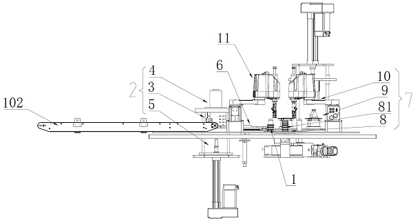
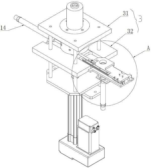
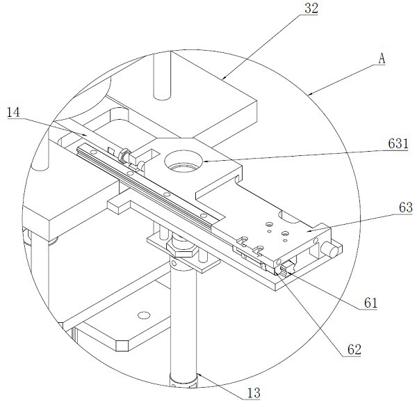
[0055] see figure 1 , figure 2 , Figure 4 , Figure 6 , Figure 7 , Figure 8 , Figure 13 , Figure 14 and Figure 15 As shown, a piston lagging production line, which wraps the film 1 on the piston ring 101 to make piston lagging, has:

[0056] The conveying line 102 for the product to be processed that conveys the piston ring 101;

[0057] A turntable 8 for conveying the film 1;

[0058] A pre-encapsulation device 7 for pre-encapsulating the film 1 on the piston ring 101;

[0059] A forming device 2 for forming the pre-encapsulated piston ring 101;

[0060] Transferring the film 1 and piston ring 101 to the pre-encapsulation device 7, and transferring the pre-encapsulated piston ring 101 to the forming device 2, and transferring the piston encapsulation to a finished product delivery line 103;

[0061] A turntable 9 with a feed...


PUM


Abstract

The invention discloses a piston rubber coating production line, and aims to provide the piston rubber coating production line which is efficient in production, high in yield and high in applicability, and the key points of the technical scheme are as follows: the piston rubber coating production line is sequentially provided with a to-be-processed product conveying line for conveying a piston ring; a turntable used for conveying a rubber sheet; a pre-rubber-coating device used for pre-rubber-coating the rubber sheet on the piston ring; a forming device used for forming the pre-encapsulated piston ring; a transfer device used for transferring the rubber sheet and the piston ring to the pre-rubber-coating device, transferring the pre-rubber-coated piston ring to the forming device and transferring the piston rubber coating to a finished product conveying line; and a rotary frame provided with a feeding station, a machining station, a finishing station and a material taking station, a pressing head correspondingly arranged above the machining station and has a vertical reciprocating motion process, and a core rod used for installing the rubber sheet. The invention is applicable to the technical field of damper piston production equipment.

Description

technical field [0001] The invention relates to the technical field of production equipment for shock absorber pistons, and more precisely relates to a production line for rubber covering of pistons. Background technique [0002] In the suspension system, the elastic elements vibrate due to the impact. In order to improve the smoothness and comfort of the car, a shock absorber is installed in parallel with the elastic elements in the suspension. When there is relative motion between the frame and axle due to vibrations, the piston in the shock absorber moves up and down. Due to the frequent relative movement between the piston and the shock absorber cylinder, it is necessary to coat the surface of the piston with a wear-resistant and low-friction material, such as polytetrafluoroethylene, to prolong the service life. [0003] The existing methods of piston rubber wrapping mainly include: manually place the rubber covering on the piston, use a manual pressing mechanism to pu...

Claims


Application Information

Patent Timeline
Patent Type & Authority Applications(China)
IPC IPC(8): B29C65/18B29C65/78B29C65/80
CPCB29C65/18B29C65/7861B29C65/80B29C66/742
Inventor 邬赛尧
Owner 宁波骏马新材料科技有限公司
Why Eureka
Try Eureka