Cast-in-place concrete pile with expanded-diameter threaded pile section, drill bit device for pile forming and pile forming method

A technology for concrete and cast-in-place piles, which is applied to drill bits, earthwork drilling, sheet pile walls, etc., can solve the problems of insufficient use of pile bottom soil stress, many human factors in the reinforcement of original soil layers, and large differences in reinforcement results. Achieve the effect of saving pile material, increasing the effective circumferential area, and strong pull-out ability

Pending Publication Date: 2021-01-22
刘守进 +1
View PDF0 Cites 1 Cited by
  • Summary
  • Abstract
  • Description
  • Claims
  • Application Information

AI Technical Summary

Problems solved by technology

But there are also serious deficiencies: one is that the same pile needs to be constructed twice, and the construction cost is high; the other is that grout is poured into the ground, which pollutes the groundwater environment; This leads to large differences in reinforcement results; fourth, the cost of pile formation is high; fifth, this type of pile is mostly based on side resistance, and the soil stress at the bottom of the pile has not been fully utilized

Method used


Image

  • Cast-in-place concrete pile with expanded-diameter threaded pile section, drill bit device for pile forming and pile forming method
  • Cast-in-place concrete pile with expanded-diameter threaded pile section, drill bit device for pile forming and pile forming method
  • Cast-in-place concrete pile with expanded-diameter threaded pile section, drill bit device for pile forming and pile forming method

Examples


Embodiment 1

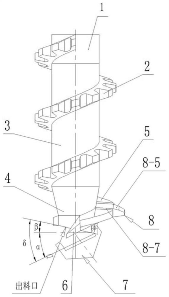
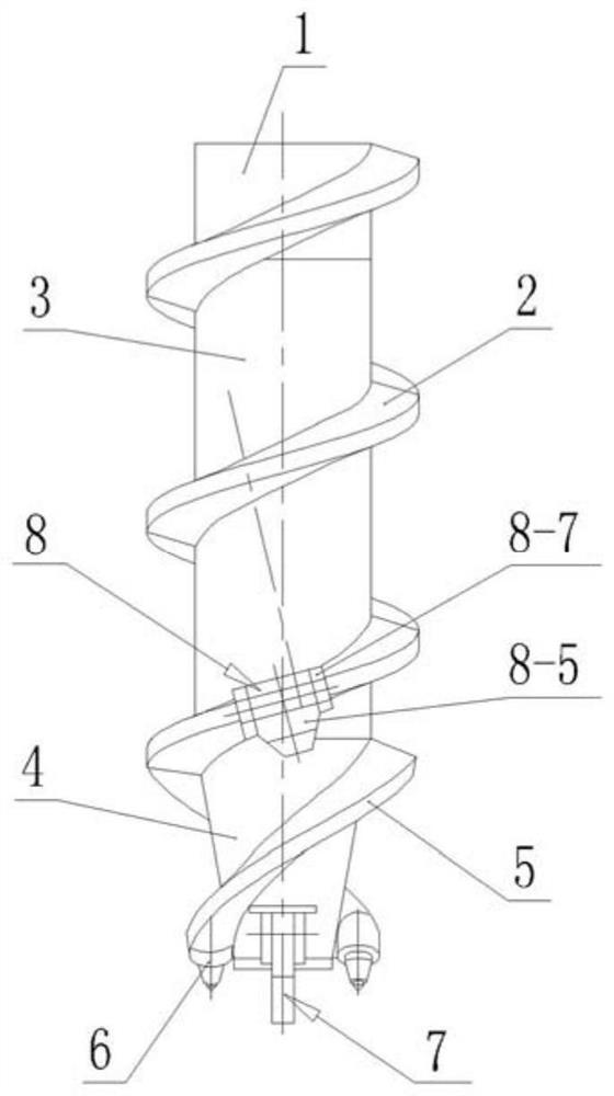
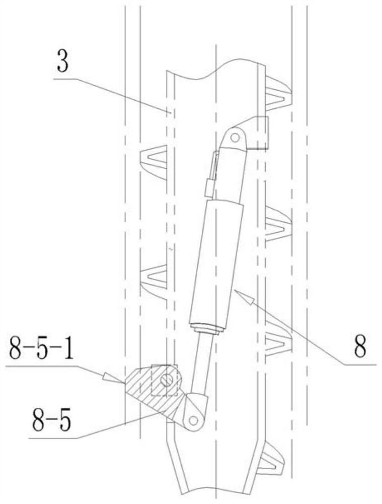
[0060] like Figure 1-Figure 12 As shown, a drill bit device for concrete pouring pile with enlarged diameter screw pile section, including joint (1), spiral blade I (2), core pipe I (3), core pipe II (4), Helical blade II (5), cutting teeth (6), drill point device (7) and rotary slider mechanism (8).

[0061] Joint (1), core pipe I (3) and core pipe II (4) are sequentially fixed coaxially to form an integrated structure, and there is a channel for concrete to pass through inside, and the joint (1) and core pipe I (3) The outer surface of the spiral blade I (2) is wound, the outer surface of the core tube II (4) is wound with the spiral blade II (5), and the upper end surface of the spiral blade II (5) is correspondingly connected with the lower end surface of the spiral blade I (2) , The lower end of the helical blade II (5) is provided with cutting teeth (6). The drill point device 7 is located at the lower end of the core pipe II4.

[0062] In one embodiment, the piling ...

Embodiment 2

[0085] (1) Structure of concrete pouring pile with enlarged diameter screw pile section

[0086] like Figure 13-Figure 18 Shown, a kind of concrete cast-in-place pile with enlarged diameter screw tooth pile section comprises concrete main body pile (10), and described concrete main body pile (10) is made of pile bottom (11), pile body part (12) and pile top ( 13) Composition.

[0087] The shape of the bottom of the pile (11) is an enlarged head structure (14) formed by extending the concrete main pile (10) to the surroundings through multiple compacted concrete.

[0088] A thread pile section (15) is provided, and the thread pile section (15) is an outwardly protruding spirally coiled thread (17) with an integral structure formed on the outer edge of the concrete main body pile (10); The section of the thread (17) is trapezoidal; the threaded pile section (15) is arranged on the pile body (12) and / or the pile top (13).

[0089] There is at least one section of enlarged-dia...


PUM


Abstract

The invention relates to a cast-in-place concrete pile with an expanded-diameter thread pile section, a drill bit device for pile forming and a pile forming method. The cast-in-place concrete pile with the expanded-diameter threaded pile section comprises a concrete main body pile, and the concrete main body pile is composed of a pile bottom, a pile body and a pile top; the shape of the pile bottom is an expanded head structure formed by extending the concrete main body pile to the periphery through re-compacted concrete; the cast-in-place concrete pile is provided with a thread pile section and at least one expanded-diameter thread pile section, and the thread pile section is formed by spirally coiling threads which are of an integrated structure and protrude outwards on the outer edge ofthe concrete main body pile; the expanded-diameter threaded pile section is formed by extending part of the threaded pile section to the periphery through re-compacted concrete, and the outer diameter of the outer edge of the expanded-diameter threaded pile section is larger than that of the outer edge of the threaded pile section; and the thread pile section and the expanded-diameter thread pilesection are arranged on the pile body and / or the pile top. The cast-in-place concrete pile is suitable for soil layers such as filled soil, cohesive soil, silt and sandy soil, one-time pile forming is achieved, and the high bearing capacity is achieved.

Description

technical field [0001] The invention belongs to the field of building construction foundation pile construction, and in particular relates to a concrete pouring pile with an enlarged-diameter screw pile section, a drill bit device for pile formation, and a pile formation method. Background technique [0002] In the existing building pile foundation construction, for the geological conditions of cohesive soil, silt soil, sandy soil and filling soil, the soil around the pile is mostly reinforced with cement slurry, and then the construction of rigid concrete piles is carried out, so that Get a higher carrying capacity. But there are also serious deficiencies: one is that the same pile needs to be constructed twice, and the construction cost is high; the other is that grout is poured into the ground, which pollutes the groundwater environment; This leads to large differences in reinforcement results; fourth, the cost of pile formation is high; fifth, this type of pile is mainl...

Claims


Application Information

Patent Timeline
Patent Type & Authority Applications(China)
IPC IPC(8): E02D5/34E02D5/48E02D5/72E02D15/04E21B10/32
CPCE02D5/34E02D5/48E02D5/72E02D15/04E21B10/32
Inventor 刘守进张喜才赵世范方光秀赵越杨延君吴建祥安志宏李俊阳高峰黄健张夏枭白忠海
Owner 刘守进
Why Eureka
Try Eureka