
Hydraulic jet grouting drill bit

A drill bit and hydraulic technology, applied in the field of petroleum exploration, can solve the problems of restricting the drilling efficiency and drilling depth of branch pipes, it is difficult to have a hollow structure with large power output, and it does not have the function of rotary drilling, etc., so as to improve drilling efficiency , Improve the drilling depth and the effect of flexible structure

Active Publication Date: 2021-01-22
BEIJING INST OF EXPLORATION ENG
View PDF7 Cites 0 Cited by
  • Summary
  • Abstract
  • Description
  • Claims
  • Application Information

AI Technical Summary

Problems solved by technology

However, the drill bit at the front end of the branch pipe is usually designed to break the rock by hydraulic jet, which does not have the function of rotary drilling and cannot penetrate the reservoir efficiently, which restricts the drilling efficiency and depth of the branch pipe.
In addition, the existing drilling bits for petroleum and geological exploration require a huge power system to drive, which consumes a lot of energy, and it is difficult for most bottom-hole power transmission mechanisms such as screws and turbines to achieve a large power output with a hollow structure

Method used


Image

  • Hydraulic jet grouting drill bit
  • Hydraulic jet grouting drill bit
  • Hydraulic jet grouting drill bit

Examples


Embodiment Construction

[0035] Below in conjunction with accompanying drawing, the present invention will be further described:

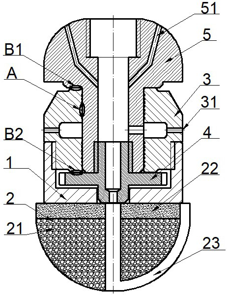
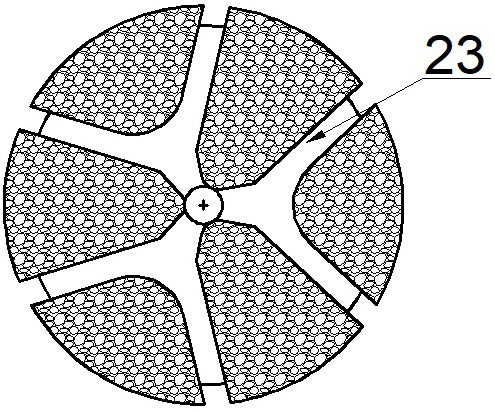
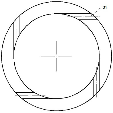
[0036] Figure 1 to Figure 5 It shows the first embodiment of a hydrodynamic rotary jet drill bit of the present invention. figure 1 , Figure 4 and Figure 5 It is a schematic diagram of the structure of the hydrojet drill bit in this embodiment; figure 2 It is a structural schematic diagram of cutting block in this embodiment; image 3 It is a schematic diagram of the arrangement of eccentric nozzles on the rotating body in this embodiment.

[0037] Such as figure 1 As shown, the hydrojet drill bit in this embodiment includes a drill steel body 1, a top wire 4 and a mandrel 5. One end of the drill steel body 1 is provided with a cutting tire block 2, and the other end is connected with the rotating body 3. The core One end of the shaft 5 passes through the hollow part of the rotating body 3 and is connected with the top wire 4. The top wire 4 is arranged in the ho...


PUM


Abstract

The invention relates to a hydraulic jet grouting drill bit. The hydraulic jet grouting drill bit is characterized in that the hydraulic jet grouting drill bit comprises a drill bit steel body, a jackscrew and a mandrel, a cutting blank block is arranged at one end of the drill bit steel body, the other end of the drill bit steel body is connected with a rotating body, and one end of the mandrel penetrates through a hollow part of the rotating body to be connected with the jackscrew. The jackscrew is arranged in the hollow part of the drill bit steel body, and a central hole of the jackscrew,a central hole of the mandrel and a central hole of the cutting blank block share the same central line. A rotational flow cavity is formed in the rotating body and communicates with the center hole of the mandrel, and one or more sets of eccentric rotating nozzles are further arranged on the rotating body and communicate with the rotational flow cavity. A plurality of propelling nozzles are further arranged at the tail of the drill bit and communicate with the central hole of the mandrel. High-pressure liquid flow is adopted as a driving source to generate rotating power, rear propelling force and front-end high-pressure jet flow, the jet flow rock breaking capacity is achieved, the drilling efficiency and the drilling depth can be improved, and extra large power system driving is not needed.

Description

technical field [0001] The invention belongs to the technical field of petroleum exploration, and in particular relates to a hydraulic rotary jet drill bit. Background technique [0002] In oil production, it is an important means to connect reservoirs by drilling branch wells or pre-setting branch pipes to open up oil flow channels. Oil and gas reservoir production. However, the drill bit at the front end of the branch pipe is usually designed to break the rock by hydraulic jet, which does not have the function of rotary drilling and cannot penetrate the reservoir efficiently, which restricts the drilling efficiency and depth of the branch pipe. In addition, the existing drill bits for petroleum and geological exploration all require a huge power system to drive, which consumes a lot of energy, and most bottom-hole power transmission mechanisms such as screws and turbines are difficult to achieve large power output with hollow structures. Contents of the invention [00...

Claims


Application Information

Patent Timeline
IPC IPC(8): E21B7/18
CPCE21B7/18
Inventor 阮海龙沈立娜刘智键刘协鲁蔡家品李春赵义梁涛
Owner BEIJING INST OF EXPLORATION ENG
Learn More