Ambient air water taking device

A technology for ambient air and water intake devices, which is applied in the direction of sampling devices, water conservation, climate sustainability, etc., and can solve problems such as limiting the scope of use

Active Publication Date: 2021-01-22
TIANJIN CHENGJIAN UNIV
View PDF10 Cites 0 Cited by
  • Summary
  • Abstract
  • Description
  • Claims
  • Application Information

AI Technical Summary

Problems solved by technology

However, most of the above methods are assisted by electric power, which limits its application range
For example, the use of semiconductor cooling chips to achieve temperature reduction requires power; heat pipe technology is a mature one-way heat transfer technology. It is only suitable for the case where the lower part absorbs heat and the upper part releases heat

Method used


Image

  • Ambient air water taking device
  • Ambient air water taking device

Examples


Embodiment 1

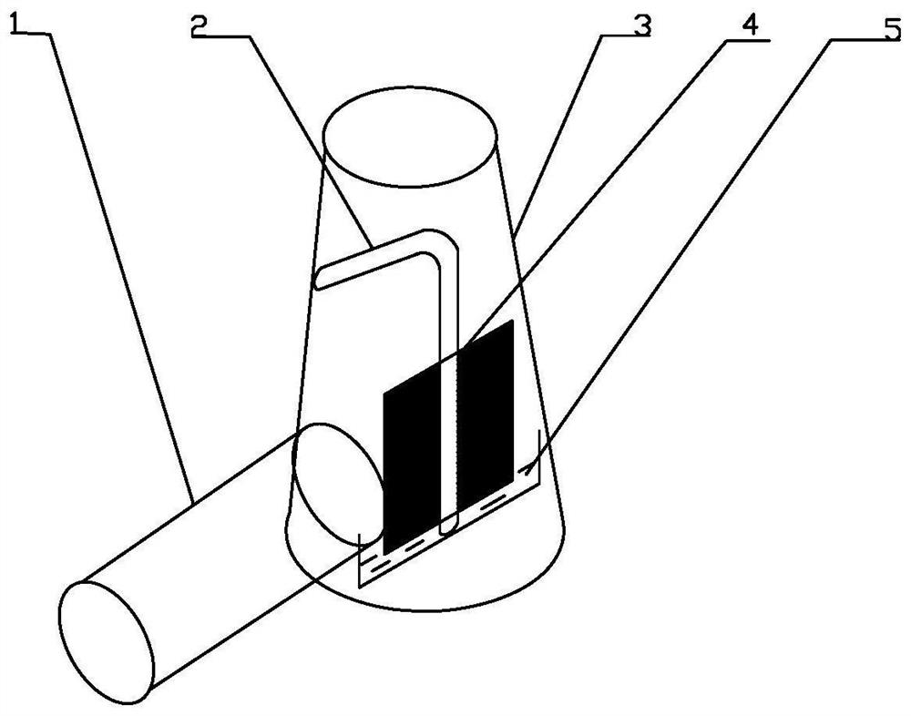
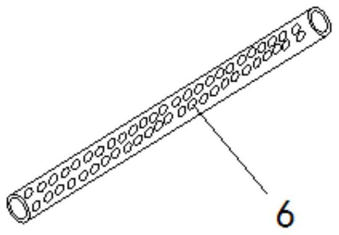
[0021] Such as Figure 1-2 As shown, an ambient air water intake device provided in this embodiment includes an air intake channel 1, a heat pipe 2, an air outlet chimney 3, and a plurality of porous finned tubes 4; the porous finned tubes 4 are made of heat-conducting materials, and their surface A plurality of finned tube openings 6 are provided, and the aperture diameter of the finned tubes is below 2mm; the heat pipe 2 is located in the air outlet chimney 3, and the condensation end of the heat pipe 2 passes through the side wall of the air outlet chimney 3 Inserted into the soil, a plurality of porous finned tubes 4 are fixedly installed on the outer wall of the evaporation end of the heat pipe 2, a water accumulation tank 5 is arranged below the porous finned tubes 4, and one end of the air intake channel 1 is connected to the air The side wall of the gas outlet chimney 3 is connected, and the connection is opposite to the evaporation end of the heat pipe 2;

[0022] Th...

Embodiment 2

[0028] Use the ambient air water intake device in Example 1 for water intake: the ambient air temperature is 29°C, the relative humidity is 90%, the soil temperature is 21°C, the opening rate of the porous finned tube is 50%, the aperture is 1.5mm, and 800mL of fresh water is obtained in 5 hours.

Embodiment 3

[0030] Use the ambient air water intake device in Example 1 for water intake: the ambient air temperature is 32°C, the relative humidity is 50%, the soil temperature is 26°C, the opening rate of the clustered porous finned tube is 50%, and the aperture is 1mm, and 260mL of fresh water is obtained in 5 hours.


PUM

PropertyMeasurementUnit
pore sizeaaaaaaaaaa

Abstract

The invention relates to an ambient air water taking device. The device comprises an air inlet channel, a heat pipe, an air outlet chimney and a plurality of porous finned tubes; the porous finned tubes are made of heat conduction materials, a plurality of finned tube holes are formed in the surfaces of the porous finned tubes, and the hole diameters of the finned tube holes are smaller than 2 mm.The heat pipe is arranged in the air outlet chimney, a condensation end of the heat pipe penetrates through the side wall of the air outlet chimney to be inserted into soil, the multiple porous finned pipes are fixedly installed on the outer wall of an evaporation end of the heat pipe, and a water accumulation groove is formed below the porous finned pipes. One end of the air inlet channel communicates with the side wall of the air outlet chimney, and the communicating position faces the evaporation end of the heat pipe. The air outlet chimney is partially arranged in ground soil, and the end, connected with ambient air, of the air inlet channel is lower than the end, located at the upper end of the ground, of the air outlet chimney. Water is taken by means of the synergistic effect of temperature drop and the micro-interface mesoscopic effect, and the fresh water obtaining amount is increased.

Description

technical field [0001] The invention belongs to fresh water acquisition technology, in particular to an ambient air water intake device. Background technique [0002] Water is the source of human life and the foundation of life on earth. However, access to fresh water is especially important in the wild where there are no water sources or little rainfall. The moisture in the air comes from the natural evaporation of water sources such as surface water or ocean water. The air humidity indicates the moisture content in the air. The higher the air temperature, the more moisture it can hold. Water can be evaporated or condensed by using temperature difference or pressure change: increasing the pressure requires mechanical pressurization, which means power consumption; lowering the temperature below the dew point can also condense the gaseous water molecules in the air into liquid water. However, most of the above methods are assisted by electric power, which limits the scope o...

Claims


Application Information

Patent Timeline
Patent Type & Authority Applications(China)
IPC IPC(8): G01N1/28G01N1/10
CPCG01N1/28G01N1/10Y02A20/00
Inventor 苏润西
Owner TIANJIN CHENGJIAN UNIV
Why Eureka
Try Eureka