
Power failure monitoring method and device, electronic equipment and computer readable storage medium

A technology of electronic equipment and storage media, which is applied to the detection of faulty computer hardware, faulty hardware testing methods, calculations, etc., and can solve problems such as power loss and inability to record logs

Inactive Publication Date: 2021-01-22
SUZHOU LANGCHAO INTELLIGENT TECH CO LTD
View PDF0 Cites 5 Cited by
  • Summary
  • Abstract
  • Description
  • Claims
  • Application Information

AI Technical Summary

Problems solved by technology

[0005] The purpose of the present invention is to provide a power failure monitoring method, device, electronic equipment and computer-readable storage medium, to solve the technical problem that the log cannot be recorded when the power supply is lost or a serious failure occurs in the prior art

Method used


Image

  • Power failure monitoring method and device, electronic equipment and computer readable storage medium
  • Power failure monitoring method and device, electronic equipment and computer readable storage medium
  • Power failure monitoring method and device, electronic equipment and computer readable storage medium

Examples


Embodiment 1

[0059] 1) PSU information detection design

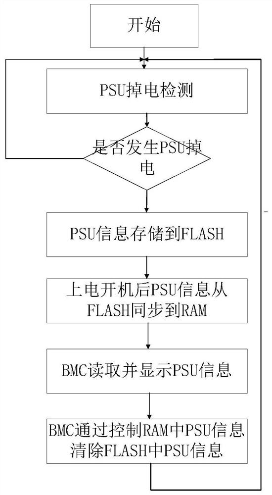
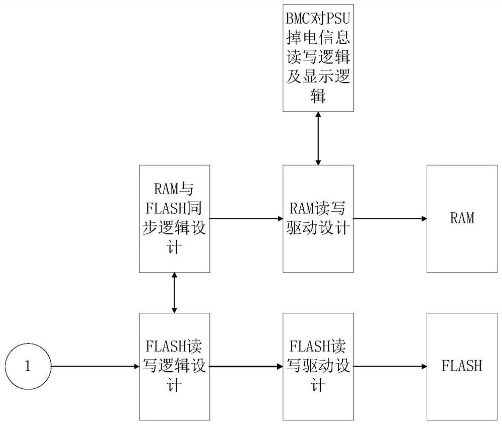
[0060] Through the CPLD / FPGA high-speed system clock, the falling edge of the PWROK signal indicating that the working status information of each PSU is normal is monitored in real time. When all PSU PWROK signals are detected to be abnormal, the PSU power-off indication signal is obtained. Schematic diagram of PSUPWROK power supply indication detection module function such as figure 2 shown.

[0061] 2) FLASH reading design

[0062] When the PSU PWROK signal is abnormal, write operation to FLASH, especially, this is carried out by following the FLASH timing through the state machine. When the PSU PWROK signal returns to normal, perform a read operation on the FLASH. When the upper controller clears the FLASH PSU indicator bit, it writes the FLASH PSU indicator bit and writes the current PSU PWROK normal information. In particular, for CPLD, PSU information can be stored in its own user FLASH, and for FPGA, PSU information can ...

Embodiment 2

[0068] 1) based on embodiment one principle based on CPLD / FPGA and BMC design switch PSU power down failure information record and display system;

[0069] 2) Compile the CPLD / FPGA and BMC program, and update the CPLD / FPGA and BMC burning image;

[0070] 3) Plug and unplug the PSU, verify the effectiveness of the strategy and optimize the PSU power-down information recording and protection system of the switch.

[0071] The PSU power-off information recording and display system proposed by the present invention can not only be applied to the switch system, but also can be used in the server system. At the same time, FLASH can not only record the PSU power-off information, but also can record any information that is lost or expected to be saved when the power is off.

[0072] It should be noted that like numerals and letters denote similar items in the following figures, therefore, once an item is defined in one figure, it does not require further definition and explanation in ...


PUM


Abstract

The invention provides a power failure monitoring method and device, electronic equipment and a computer readable storage medium, belongs to the technical field of power failure monitoring, and solvesthe problem that in an existing control strategy, logs are not recorded even if a power supply is seriously lost and a fault occurs. The method comprises the steps: when a power supply unit is powered down, storing power down information in a flash memory; after the power supply unit is powered on again, reading the power failure information in the flash memory; synchronizing the power failure information to the RAM, so that the BMC can read the power failure information in the RAM; and clearing the power failure information in the flash memory. The method and device are used for adding a switch PSU power-down information recording and displaying function into an existing CPLD / FPGA and BMC design, the switch fault recording and displaying system design is optimized, the PSU power-down information recording and displaying system facilitates problem positioning when a fault occurs, and after the BMC obtains the power-down information, a power-down log needs to be recorded besides a clearing action, therefore, a user is prompted, and a more humanized interactive design is brought to the user.

Description

technical field [0001] The present invention relates to the technical field of power failure monitoring, in particular to a power failure monitoring method, device, electronic equipment and computer-readable storage medium. Background technique [0002] CPLD / FPGA is a semi-custom application-specific integrated circuit, which has a series of advantages such as flexible programming, fast response, and high integration. It has been more and more widely used in the field of early development verification and control applications. In the switch system, the power-on and power-off sequence control, communication control, button detection, fan speed control, SFP lighting control and serial port switching of the entire switch are controlled through the CPLD / FPGA chip, and the switch status, status detection, and firmware upgrade are indicated through the BMC. , remote control and log collection, etc. [0003] When the power supply of the switch system is lost due to the loss of the...

Claims


Application Information

Patent Timeline
IPC IPC(8): G06F11/22G06F11/14
CPCG06F11/1446G06F11/2273
Inventor 季冬冬张广乐刘畅
Owner SUZHOU LANGCHAO INTELLIGENT TECH CO LTD
Learn More