
Integrated hydrogen circulating pump in fuel cell system

A fuel cell system and circulating pump technology, applied to fuel cells, fuel cell additives, electrical components, etc., can solve problems such as rotor misalignment, leakage of hydrogen circulating pump, shortening the service life of hydrogen circulating pump, etc. non-concentric effect

Pending Publication Date: 2021-01-22
苏州瑞驱电动科技有限公司 +1
View PDF2 Cites 1 Cited by
  • Summary
  • Abstract
  • Description
  • Claims
  • Application Information

AI Technical Summary

Problems solved by technology

At present, the motor of the hydrogen circulation pump mostly adopts a permanent magnet synchronous motor, and the installation method of the drive motor is mostly installed independently with a keyway or a spline connection. The installation is time-consuming and inconvenient to operate, and it is easy to cause the rotor of the motor to be out of alignment with the rotor of the hydrogen circulation pump , which shortens the service life of the hydrogen circulation pump; the working medium of the hydrogen circulation pump is high-temperature circulating hydrogen, and because the molecular weight of hydrogen is small, it is easy to cause leakage of the hydrogen circulation pump during operation; the hydrogen circulation pump is still in high temperature and high humidity. It is easy to have a large amount of liquid water in the rotor cavity during use, and the accumulated liquid water will easily cause the hydrogen circulation pump to be difficult to start when it encounters a low temperature environment. Therefore, an integrated hydrogen gas in the fuel cell system is required. The circulation pump improves the above problems

Method used


Image

  • Integrated hydrogen circulating pump in fuel cell system
  • Integrated hydrogen circulating pump in fuel cell system
  • Integrated hydrogen circulating pump in fuel cell system

Examples


Embodiment

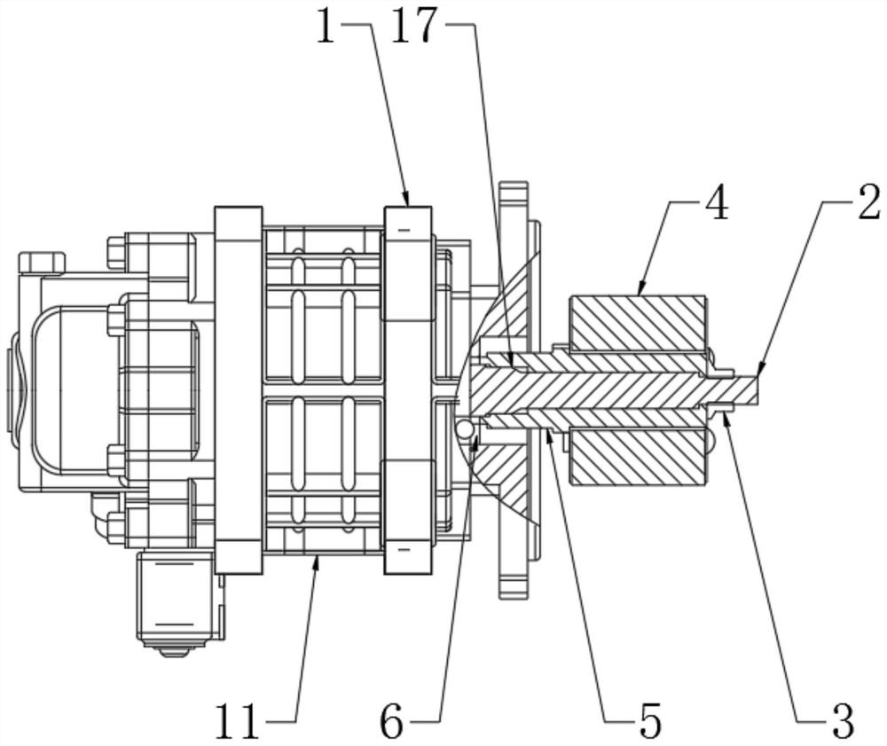
[0028] Solve the non-concentricity problem between the permanent magnet synchronous motor rotor assembly and the shaft 2 by detecting the amount of rotor runout after installation; pass the water injection and freezing test on the casing of the hydrogen circulation pump by simulating the operating conditions, and it can start normally under low temperature conditions; through the integration The motor part of the hydrogen circulation pump is tested for airtight helium leakage, so that the sealing problem of the motor is solved.


PUM


Abstract

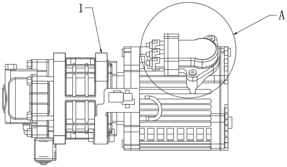
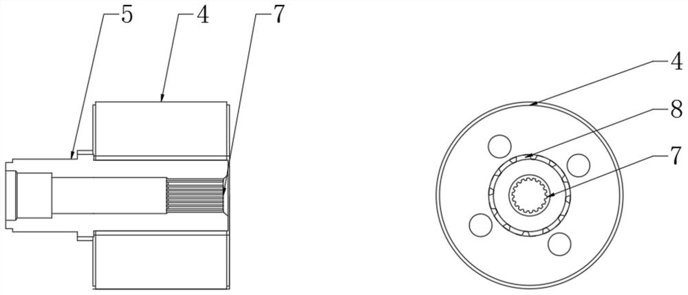
The invention relates to the technical field of hydrogen fuel cells, particularly to an integrated hydrogen circulating pump in a fuel cell system. The integrated hydrogen circulating pump comprises ahydrogen circulating pump, wherein a motor driving shaft is arranged in the middle of the hydrogen circulating pump, a spline shaft sleeve is arranged outside the motor driving shaft, a permanent magnet synchronous motor rotor is arranged outside the spline shaft sleeve, a shaft sleeve front section interference fit face is arranged in the middle of the outer portion of the motor driving shaft, aflange face installation screw is arranged on the side, away from the shaft sleeve front section interference fit face, of the outer portion of the motor driving shaft, a bearing is arranged at the position, close to the shaft sleeve front section interference fit face, of the outer portion of the motor driving shaft, an involute internal spline is arranged at the position, close to the flange face installation screw, in the spline shaft sleeve, a rectangular tooth groove is formed in the permanent magnet synchronous motor rotor, a shoulder step is arranged at the position, close to the shaftsleeve front section interference fit face and the middle of the permanent magnet synchronous motor rotor, outside the spline shaft sleeve, a flat square is arranged on the shoulder step. According to the invention, the overall effect is good.

Description

technical field [0001] The invention relates to the technical field of hydrogen fuel cells, in particular to an integrated hydrogen circulation pump in a fuel cell system. Background technique [0002] Hydrogen fuel cell vehicles use the charge transfer during the chemical reaction between hydrogen and oxygen to form an electric current, thereby directly converting chemical energy into electrical energy to drive the motor of the vehicle. In order to prevent the discharge of hydrogen gas that chemically reacts with oxygen to ensure the service life of the hydrogen fuel cell, after the chemical reaction between oxygen and hydrogen inside the hydrogen fuel cell, excess hydrogen needs to be recovered through a hydrogen circulation pump. At present, the motor of the hydrogen circulation pump mostly adopts a permanent magnet synchronous motor, and the installation method of the drive motor is mostly installed independently with a keyway or a spline connection. The installation is ...

Claims


Application Information

Patent Timeline
IPC IPC(8): H01M8/04082H01M8/04089
CPCH01M8/04097H01M8/04089H01M8/04201Y02E60/50
Inventor 刘善波李建军
Owner 苏州瑞驱电动科技有限公司
Learn More