UAV terminal laser energy transfer system based on three-level tracking and light field control

A technology of laser energy transmission and unmanned aerial vehicles, which is applied in the direction of optics, optical components, and the control of finding targets, can solve problems such as uneven energy distribution of laser beams, no matching of photovoltaic cells, and no avoidance of dead zones at electrode connections.

Active Publication Date: 2022-07-15
SHANGHAI JIAO TONG UNIV
View PDF4 Cites 0 Cited by
  • Summary
  • Abstract
  • Description
  • Claims
  • Application Information

AI Technical Summary

Problems solved by technology

However, the efficiency of photovoltaic cells used in the existing transmitting end is about 10-20%, which is far below the requirements of practical applications, and the high-energy laser energy cannot be fully utilized.
The main limiting factors of terminal photoelectric conversion efficiency are the terminal laser energy distribution and the adaptation of photovoltaic cells
At present, the Gaussian beam is mainly shaped into a flat-top beam by light field regulation to improve the photoelectric conversion efficiency. However, it has not matched the arbitrary arrangement of photovoltaic cells, nor avoided the dead zone at the electrode connection.
The energy distribution of the laser beam is not uniform, and the hot spot effect generated will also lead to a decrease in the efficiency of the photovoltaic cell receiver

Method used


Image

  • UAV terminal laser energy transfer system based on three-level tracking and light field control
  • UAV terminal laser energy transfer system based on three-level tracking and light field control
  • UAV terminal laser energy transfer system based on three-level tracking and light field control

Examples


Embodiment Construction

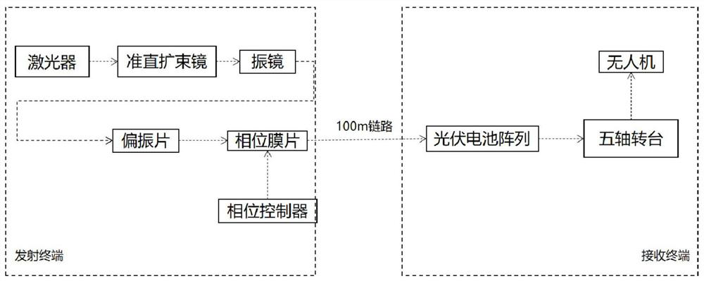
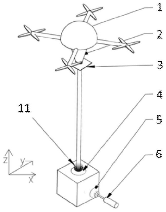
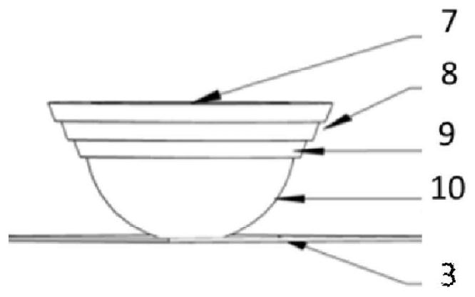
[0036] like Figure 1 to Figure 3 As shown, this embodiment relates to a UAV terminal laser energy transmission system based on three-level tracking and phase modulation, including: UAV 1, terminal five-axis turntable 2, photovoltaic cell array bearing module 3, tracking galvanometer Unit 4, spatial light phase modulation diaphragm 11, collimating beam expanding module 5 and high-power laser 6, wherein: Gaussian laser firstly conducts beam collimation beam expansion and energy homogenization through the collimating beam expanding system to make the diameter of the spot After reaching a suitable range covering the spatial light phase modulation film, the light field tracking UAV is coarsely adjusted by the galvanometer tracking device. The Gaussian light after beam expansion passes through the polarizer and then is modulated in real time by the space light phase modulation film. The optical field modulates the Gaussian optical field of the laser into an optimal optical field su...


PUM


Abstract

A laser energy transfer method for a UAV terminal based on three-level tracking and phase modulation, comprising: a high-power laser, a collimating beam expander for laser collimation and beam expansion, and a tracking for coarse tracking at the transmitting end Galvanometer unit, communication module for information transmission between transmitter and drone, polarizer, spatial light phase modulation film, drone, and terminal five-axis for visual self-alignment arranged thereon A turntable and a photovoltaic cell array, in which: the laser emitted by the high-energy laser is collimated and expanded by a collimating beam expander, and the laser is used for rough tracking of the UAV through the tracking galvanometer unit; the spatial light phase modulation diaphragm is placed on the transmitter The terminal combines the light field optimization method with real-time feedback to modulate the Gaussian light field to adapt to the arbitrary arrangement of photovoltaic cells; the tracking galvanometer unit makes the laser spot align with the photovoltaic cells; the terminal five is set on the UAV at the receiving end The axis turntable performs fine-tuning and tracking on the photovoltaic cell array to achieve the optimal receiving angle and receiving position; the photovoltaic cell array is arranged on the terminal five-axis turntable and is used to receive the modulated laser energy.

Description

technical field [0001] The invention relates to a technology in the field of high-energy laser wireless energy transmission, in particular to a UAV terminal wireless laser energy transmission system based on three-level tracking and light field regulation. Background technique [0002] High-energy laser wireless power transmission technology (Optical wireless power transmission, OWPT) is a technology that uses laser as a carrier, that is, the transmitting end converts electrical energy into laser energy and transmits it to the receiving end, and the receiving end converts light into electrical energy for charging. However, the efficiency of the photovoltaic cells used at the existing transmitter is about 10-20%, which is far lower than the requirements of practical applications, and cannot fully utilize the high-energy laser energy. The main limiting factors of the terminal photoelectric conversion efficiency are the terminal laser energy distribution and the adaptation of p...

Claims


Application Information

Patent Timeline
Patent Type & Authority Patents(China)
IPC IPC(8): H02J50/30G05D1/12G02B27/30G02B27/09
CPCH02J50/30G05D1/12G02B27/0905G02B27/30
Inventor 何祖源张文甲徐培源
Owner SHANGHAI JIAO TONG UNIV
Why Eureka
Try Eureka