
Dynamic high-precision time-frequency synchronization network

A time-frequency synchronization, high-precision technology, used in synchronization devices, time-division multiplexing systems, digital transmission systems, etc. Realize the effects of dynamic reconfiguration, high information transfer efficiency, and high synchronization accuracy

Active Publication Date: 2021-01-22
BEIJING UNIV OF POSTS & TELECOMM +1
View PDF5 Cites 6 Cited by
  • Summary
  • Abstract
  • Description
  • Claims
  • Application Information

AI Technical Summary

Problems solved by technology

[0004] 1. The network constructed by the original technical solution is a time-frequency synchronous network, which is difficult to combine with the existing high-speed data communication network. This solution uses a small amount of time-frequency dedicated data tags for data transmission, and the transmission rate is slow
[0005] 2. The network built by the original technical solution is limited by the switch design, it is difficult to deal with complex network topology and huge number of time-frequency synchronization nodes, and as the number of time-frequency synchronization nodes increases, a large number of customized switches are required, and the cost is greatly increased
[0006] 3. The network topology built by the original technology is a one-layer structure. Time-frequency signals that are far apart need to pass through multiple switches to reach the target node, and the synchronization efficiency is low.
[0007] 4. The network built by the original technology does not design an all-optical time / frequency / phase relay. In the scheme of realizing long-distance time / frequency / phase synchronization, optical-electrical-optical conversion is required, which increases signal processing delay
[0008] 5. In the original technical solution, the switch in the high-precision optical fiber time-frequency signal synchronization network did not mention the phase information

Method used


Image

  • Dynamic high-precision time-frequency synchronization network
  • Dynamic high-precision time-frequency synchronization network
  • Dynamic high-precision time-frequency synchronization network

Examples


Embodiment Construction

[0048] In order to facilitate those of ordinary skill in the art to understand and implement the present invention, the present invention will be further described in detail and in-depth below in conjunction with the accompanying drawings.

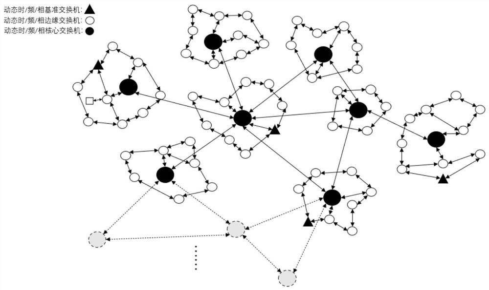
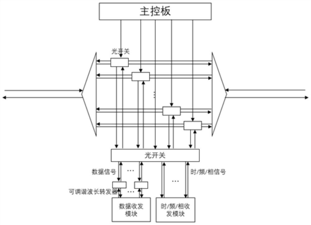
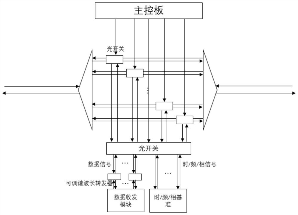
[0049] The present invention is a dynamic and high-precision time-frequency synchronization network, using time / frequency / phase switches as network nodes, and connecting the network nodes through optical fiber links; the switches include optical switches controlled by the main control board in the switch, It can quickly update the transmission path of signals between network nodes and realize the dynamic reconfiguration of the network; the network separates the transmission of time-frequency signals and data communication through wavelength division multiplexing, which can realize high-precision time-frequency transmission and high-speed transmission between nodes. data communication.

[0050] Described dynamic high-precision time-frequenc...


PUM


Abstract

The invention discloses a dynamic high-precision time-frequency synchronization network, and belongs to the field of optical fiber time-frequency signal processing and precision measurement. The time-frequency synchronization network comprises a dynamic time / frequency / phase reference switch, a dynamic time / frequency / phase core switch and a dynamic time / frequency / phase edge switch. If the local switch is an edge switch and a reference switch, the input optical signal comprises information sent to the local switch and information sent to other switches; and the local switch outputs an optical signal containing data or time / frequency / phase information, and the optical signal is combined with the optical signal of the straight-through path through the DWDM and output to the optical fiber path.If the local switch is a core switch, M paths of optical signals are input, and each path comprises N wavelength channels. The local switch outputs an optical signal containing data or time frequencyinformation, the optical path carding optical switch matrix forwards an uplink signal to a corresponding switch output port, and the uplink signal is combined with a straight-through optical signal through the DWDM and output to an optical fiber path. According to the invention, the information transmission efficiency is high, and the network dynamic reconfiguration is realized.

Description

technical field [0001] The invention belongs to the field of optical fiber time-frequency signal processing and precision measurement, and in particular relates to a dynamic high-precision time-frequency synchronization network. Background technique [0002] Optical fiber high-precision time-frequency transmission refers to the non-destructive transmission of time and frequency references using optical fiber as the medium. The generation and transmission of time-frequency standards plays a vital role in national economy, national defense construction and daily life. In the future communication network, compatible with the transmission of time-frequency information and data signals, high-precision time-frequency synchronization of each network node is undoubtedly an inevitable development direction. At present, the point-to-point time-frequency synchronization accuracy based on optical fiber transmission can reach femtosecond or even attosecond level, but the IEEE1588v2 proto...

Claims


Application Information

Patent Timeline
Patent Type & Authority Applications(China)
IPC IPC(8): H04J3/06H04L7/00
CPCH04J3/0638H04L7/00
Inventor 陈星郭弘罗斌吴腾陈子扬喻松曹义尧
Owner BEIJING UNIV OF POSTS & TELECOMM
Learn More