Stirrer for plant cell culture device

A culture device and plant cell technology, applied in tissue cell/virus culture device, biochemical cleaning device, enzymology/microbiology device, etc., can solve problems such as low degree of liquid mixing, loss of plant cell activity, cell membrane rupture, etc. , to avoid cell rupture

Inactive Publication Date: 2021-01-26
徐智勇
View PDF0 Cites 0 Cited by
  • Summary
  • Abstract
  • Description
  • Claims
  • Application Information

AI Technical Summary

Problems solved by technology

[0002] Animal and plant cell culture uses cell culture medium for stirring to provide nutrients for plant cells, so that they can get nutrients in the culture medium. Through stirring, the cells can be fully and evenly contacted with the culture medium, so as to achieve a better culture effect, and to reduce stirring The shear force of the impeller baffle agitator with a larger cut is used, but the agitator with the baffle structure will generate a large centrifugal force when the stirring speed is too fast, so that the liquid rota

Method used


Image

  • Stirrer for plant cell culture device
  • Stirrer for plant cell culture device
  • Stirrer for plant cell culture device

Examples


Embodiment 1

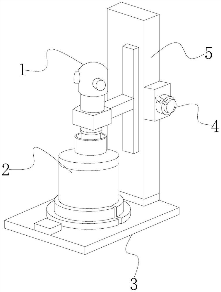
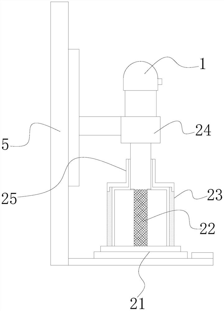
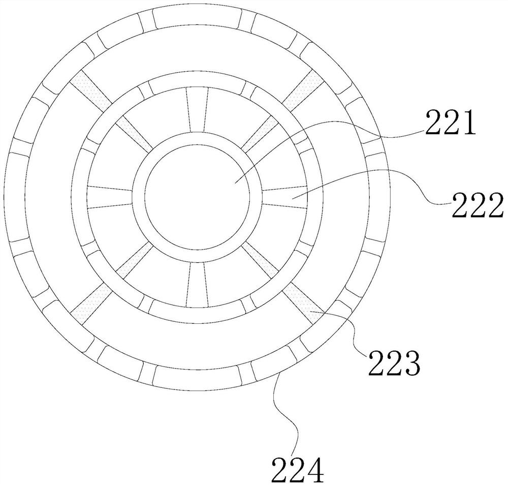
[0023] Such as Figure 1-Figure 5 Shown:

[0024] The present invention is an agitator for a plant cell culture device, its structure includes a motor 1, a stirring mechanism 2, a fixed plate 3, a controller 4, and a lifting plate 5, the motor 1 is embedded in the upper end of the agitating mechanism 2, and the The upper end of the stirring mechanism 2 is installed on the side of the lifting plate 5, the controller 4 is installed on the side of the lifting plate 5, the lower end of the stirring mechanism 2 is welded on the upper surface of the controller 4, and the lifting plate 5 is installed on the upper end of the fixed plate 3 , the stirring mechanism 2 is provided with a fixed tank 21, a stirring device 22, a placement tank 23, a fixer 24, and a blocking cover 25. , the blocking cover 25 is screwed with the placement tank 23, the lower end of the placement tank 23 is embedded in the fixing groove 21, the holder 24 is installed on the side of the lifting plate 5, and the ...

Embodiment 2

[0031] Such as Figure 6-Figure 7 Shown:

[0032] Wherein, the 233 is provided with a tilting mechanism w1, a sliding plate w2, and a drainage groove w3, the drainage groove w3 is attached to the inside of the sliding plate w2, the tilting mechanism w1 is located inside the sliding plate w2, and the sliding plate w2 is embedded Inside the fixing groove 21, the inclination angles between the drainage grooves w3 are the same, and the drainage groove w3 is a continuous curved structure, so that the liquid moves upwards following the drainage groove w3 under the action of the rotating force, thereby changing the horizontal position of the liquid.

[0033]Wherein, the tilting mechanism w1 is provided with a sealing groove w11, a force receiving block w12, a rubber plate w13, and a fixing frame w14, the sealing groove w11 is located on the right side of the rubber plate w13, and the force receiving block w12 is attached to the fixing frame w14 On the left side, the rubber plate w13...


PUM


Abstract

The invention discloses a stirrer for a plant cell culture device. The stirrer structurally comprises a motor, a stirring mechanism, a fixation plate, a controller and a lifting plate, wherein the stirring mechanism is provided with a fixation groove, a stirring device, a placing tank, a fixer and a blocking cover. Liquid generates inward force under the action of rotating force, and the effect ofreducing the rotating force is achieved; the law that liquid rotates along the inner wall is destroyed through staggering of circulating grooves, so that the liquid circulates back and forth, the pressure of rotation on the liquid is reduced, and cells in the liquid are prevented from being broken; the liquid moves upwards along drainage grooves in the inner sides of sliding plates under the action of rotating force, and therefore the horizontal position of the liquid is changed; and according to mechanical principles, liquid is expanding outwards, and moves upwards along inclined sealing grooves under the rotating force to compress sealing grooves, so that stress blocks are stressed, liquid on the inner sides of rubber plates fluctuates, the fluctuation applies upward pressure under therotating force, then the liquid is driven to be stirred upwards, and the mixing degree of the liquid is improved.

Description

technical field [0001] The invention relates to the field of animal and plant cell culture devices, in particular to a stirrer for plant cell culture devices. Background technique [0002] Animal and plant cell culture uses cell culture medium for stirring to provide nutrients for plant cells, so that they can get nutrients in the culture medium. Through stirring, the cells can be fully and evenly contacted with the culture medium, so as to achieve a better culture effect, and to reduce stirring The shear force of the impeller baffle agitator with a larger cut is used, but the agitator with the baffle structure will generate a large centrifugal force when the stirring speed is too fast, so that the liquid rotates along the inner wall of the container, which is easy to make the plant cell chloroplast Pressure is generated, which causes the rupture of the cell membrane, resulting in the loss of plant cell activity, and because the inner wall of the container is relatively smoo...

Claims


Application Information

Patent Timeline
IPC IPC(8): C12M3/00C12M1/36C12M1/02C12M1/00
CPCC12M23/38C12M23/48C12M27/02C12M27/18C12M27/22C12M41/42
Inventor 徐智勇
Owner 徐智勇
Why Eureka
Try Eureka