Guide vane for aeroacoustic wind tunnel

A guide vane and wind tunnel technology, which is applied in the field of special equipment manufacturing, can solve problems such as increasing the background of the flow channel, interfering with the test, and the resonance of the guide vane affecting the stability of the airflow, so as to ensure low resistance, reduce decibels, and reduce turbulence. Effect

Pending Publication Date: 2021-01-26
SHANGHAI DONGDING STEEL STRUCTURE
View PDF5 Cites 5 Cited by
  • Summary
  • Abstract
  • Description
  • Claims
  • Application Information

AI Technical Summary

Problems solved by technology

[0004] The purpose of the present invention is to provide a guide vane used in an aeroacoustic wind tunnel, which solves the problems in the prior art that the guide vane generates resonance, affects the stability of the airflow, and at the same time increases the background in the flow channel and interferes with the test.

Method used


Image

  • Guide vane for aeroacoustic wind tunnel
  • Guide vane for aeroacoustic wind tunnel
  • Guide vane for aeroacoustic wind tunnel

Examples


Embodiment Construction

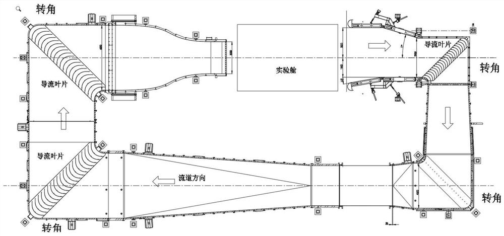
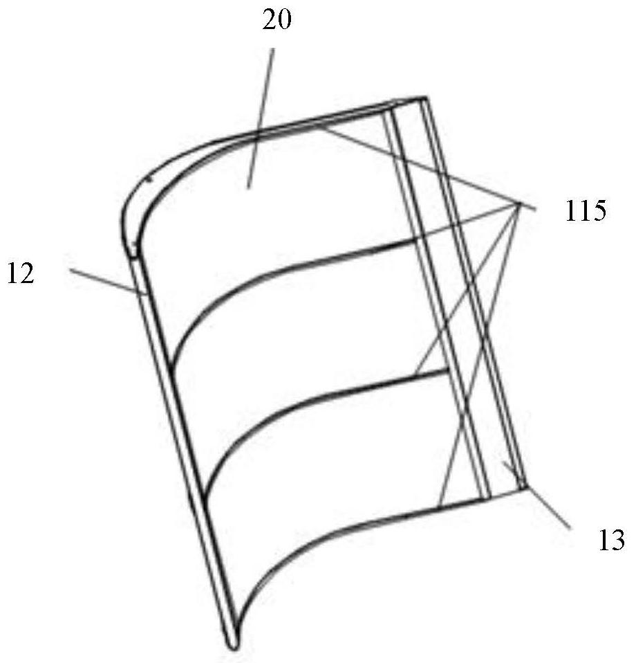
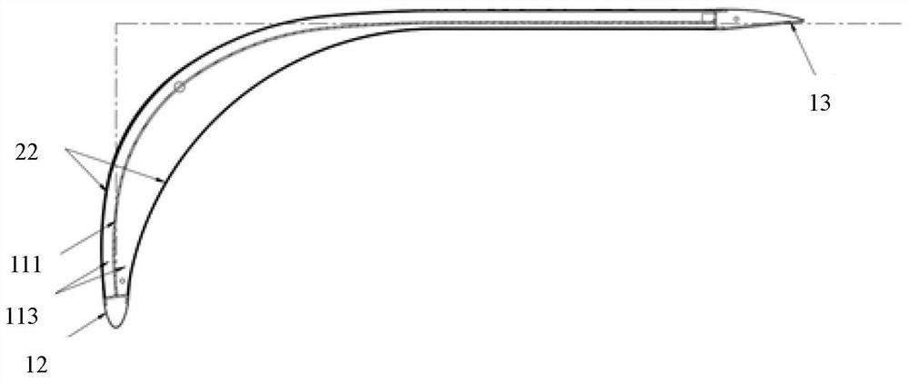
[0028] The following is attached Figure 2-8 and Specific Embodiments The guide vane used in the aeroacoustic wind tunnel proposed by the present invention will be further described in detail. The advantages and features of the present invention will become clearer from the following description. It should be noted that the drawings are in a very simplified form and all use imprecise scales, which are only used to facilitate and clearly assist the purpose of illustrating the embodiments of the present invention. In order to make the objects, features and advantages of the present invention more comprehensible, please refer to the accompanying drawings. It should be noted that the structures, proportions, sizes, etc. shown in the drawings attached to this specification are only used to match the content disclosed in the specification, for those who are familiar with this technology to understand and read, and are not used to limit the implementation of the present invention. ...


PUM


Abstract

The invention provides a guide vane for an aeroacoustic wind tunnel. The guide vane is of a streamline shape and comprises a streamline frame and a fluid sound absorption filler, the streamline frameis filled with the fluid sound absorption filler, and the external line shape of the fluid sound absorption filler is matched with the appearance of the guide vane. The streamline frame of the guide vane is filled with the fluid sound absorption filler, so that low resistance and uniformity of airflow steering can be ensured, the turbulent flow is reduced, the effects of noise elimination and reduction are achieved, the decibel of background noise of an experiment module is reduced, and therefore it is ensured that higher-quality and more accurate data are tested when a wind tunnel runs.

Description

technical field [0001] The invention relates to the technical field of special equipment manufacturing, in particular to a guide vane specially designed for an aeroacoustic wind tunnel and having a sound-absorbing effect. Background technique [0002] Aeroacoustic wind tunnels provide a closed-circuit air channel that produces a uniform circulating air flow, and are widely used in automotive testing to test the aerodynamics and aeroacoustics of large passenger cars and light trucks. Under the experimental conditions, the maximum wind speed at the nozzle of the experimental cabin can reach 250km / h, and at a wind speed of 140km / h, the background noise in the test area is only 58 decibels. In the overall flow channel of the equipment, the airflow guiding effect of the corner is particularly important. The position of the guide vane at the corner is arranged as follows: figure 1 shown. [0003] The structure of the common deflector vane used in the wind tunnel of automobile te...

Claims


Application Information

Patent Timeline
Patent Type & Authority Applications(China)
IPC IPC(8): G01M9/04
CPCG01M9/04
Inventor 吴明健
Owner SHANGHAI DONGDING STEEL STRUCTURE
Why Eureka
Try Eureka